by on ArduinoMaple Bacon

23439940833_31be1e9c50_o


Things are Different

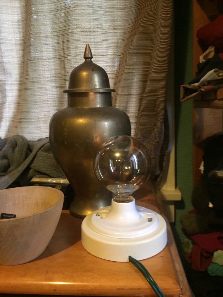
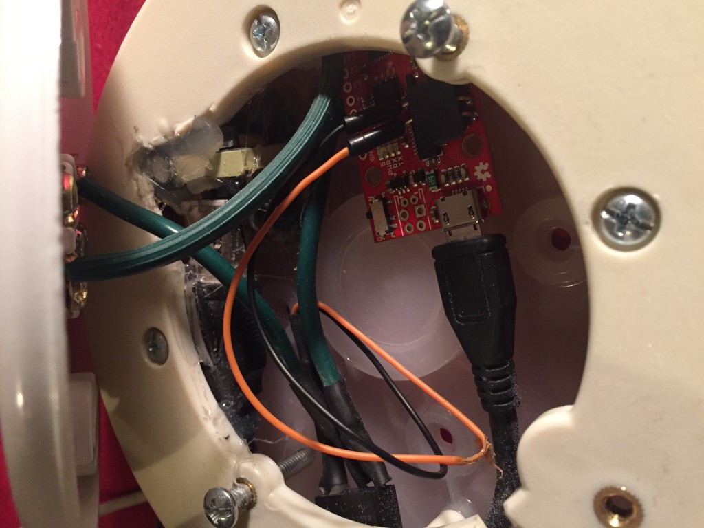
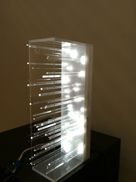
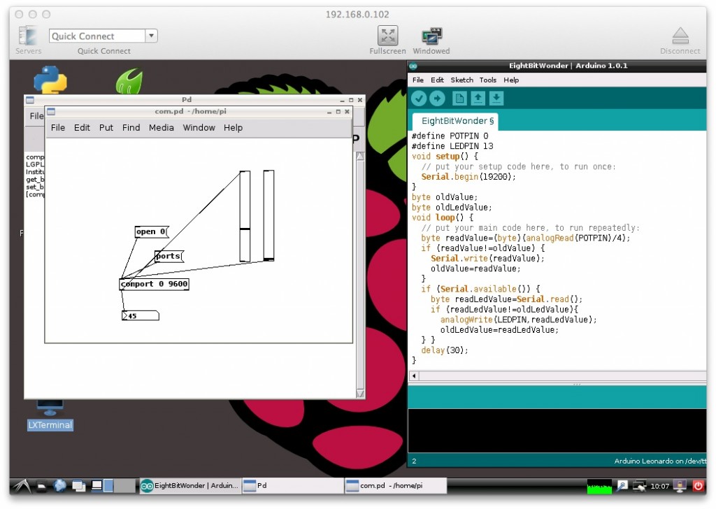
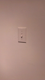
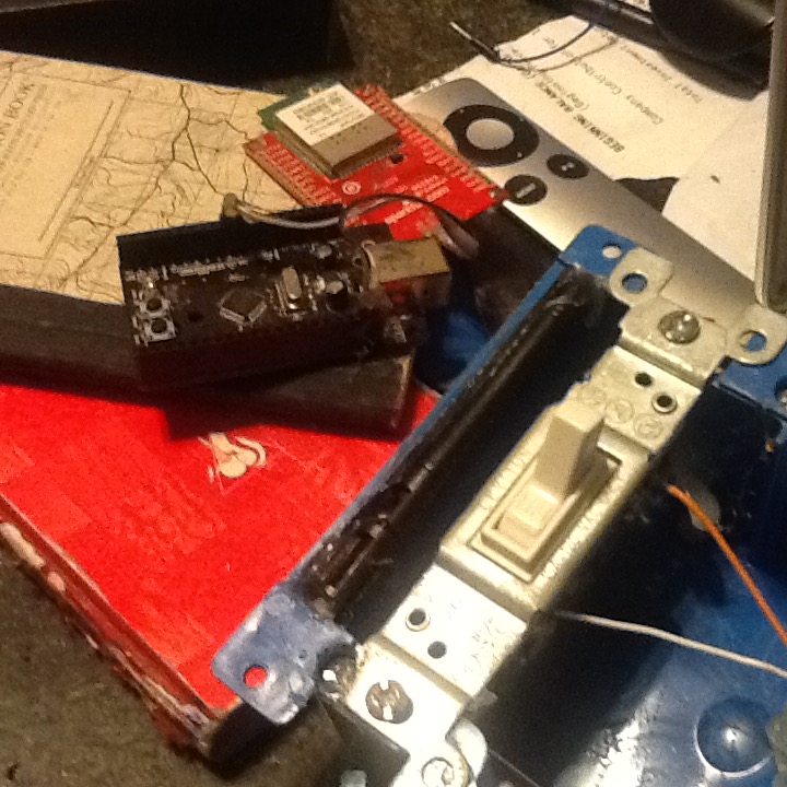
In 2012 I was struggling to put together a stm32 based wireless datalogger using leaflabs libmaple and a $20 wifi module. I had to write most of the code myself because libmaple was based on arduino-0022 and most of the wifi libraries made extensive use of the new classes available after arduino 1.xx (String for instance). It was painful and in the end the project was a complete failure except that I had a premade platform to make an art piece called Stephen Wrights Light Switch.


8346730548_dede0fa72e_n img_0935_23439975343_o

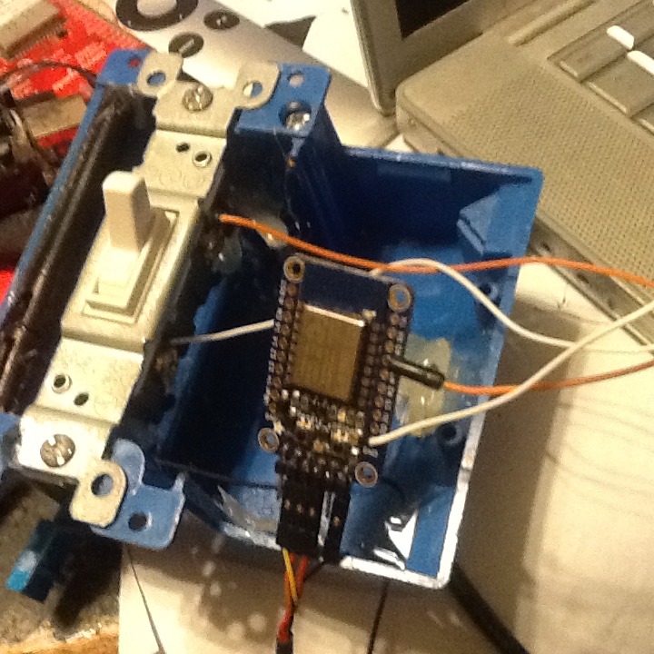
Nowadays you can get an Arduino capable wifi module for less than 10 bucks.

Huzzah!

(look it up on the internets!)


/*-----------------------------------StephenWrightsLightSwitch.ino
 This is a hack of the provided WifiClient example.
 This is free software (BSD License)
 (C) Donald Delmar Davis , SuspectDevices.

 ---------------------------------------------------------------*/


#include <ESP8266WiFi.h>


#define SWITCH_OFF 1
#define SWITCH_ON 0
#define LED_OFF 0
#define LED_ON 1


const char* ssid = "MYWIFI";
const char* password = "MYSECRET";
const char* host = "www.suspectdevices.com";
const int httpPort = 80;

const char* offstate = "OFF";
const char* onstate = "ON";

#ifdef ESP8266_DEV_BOARD
const int switchPin = 4;
const int ledPin = 5;
#else
const int switchPin = 4;
const int ledPin = 5;
#endif 
/*
 global variables
*/

bool newSwitchValueFlag = false;
bool oldSwitchValue = SWITCH_OFF;
bool lightValue = SWITCH_OFF;


/*---------------------------------------------------setup()

*/
void setup() {
 bool flipFlop = SWITCH_OFF;

 Serial.begin(115200);
 pinMode(switchPin, INPUT_PULLUP);
 pinMode(ledPin, OUTPUT);
 digitalWrite(ledPin, LED_ON);
 delay(10);

 // We start by connecting to a WiFi network

 Serial.println();
 Serial.println();
 Serial.print("Connecting to ");
 Serial.println(ssid);
 WiFi.begin(ssid, password);

 while (WiFi.status() != WL_CONNECTED) {
 flipFlop = !flipFlop;
 digitalWrite(switchPin, flipFlop);
 delay(500);
 Serial.print(".");
 }

 digitalWrite(ledPin, LED_OFF);

 Serial.println("");
 Serial.println("WiFi connected");
 Serial.println("IP address: ");
 Serial.println(WiFi.localIP());

}

/*-------------------------------------------------------------------------loop()

*/
void loop() {
 
 bool newSwitchValue;
 
 newSwitchValue = (digitalRead(switchPin)==SWITCH_ON);
 
 Serial.print("Switch="); Serial.println(newSwitchValue?"ON":"OFF");
 
 if (newSwitchValue != oldSwitchValue) {
 newSwitchValueFlag = true;
 } else {
 newSwitchValueFlag = false;
 }
 
 Serial.print("connecting to ");
 Serial.println(host);

 // Use WiFiClient class to create TCP connections
 WiFiClient client;
 if (!client.connect(host, httpPort)) {
 Serial.println("connection failed");
 return;
 }

 // We now create a URI for the request
 String url = "/art2013/settheswitch/";
 if (newSwitchValueFlag) {
 url += "?state=";
 url += newSwitchValue ? onstate : offstate;
 oldSwitchValue=newSwitchValue;
 }

 Serial.print("Requesting URL: ");
 Serial.println(url);

 // This will send the request to the server
 client.print(String("GET ") + url + " HTTP/1.1\r\n" +
 "Host: " + host + "\r\n" +
 "Connection: close\r\n\r\n");
 
 for (int t = 8; t > 0 && !client.available(); t--)
 delay(100);

 // Read all the lines of the reply from server and print them to Serial
 while (client.available()) {
 String line = client.readStringUntil('\r');
 if (line.lastIndexOf("ON") >= 0) {
 Serial.println("FOUND AN ON!!!");
 lightValue = SWITCH_ON;
 } else {
 lightValue = SWITCH_OFF;
 }

 Serial.print(line);
 }

 digitalWrite(ledPin, lightValue ? LED_ON : LED_OFF);

 Serial.println();
 Serial.println("closing connection");
 // client.close();

}

by on Arduinoarm

Background.

I was asked to put together a 2 day class on the internet of things at PNCA so I suggested that we try out the Adafruit huzzah.  while I was looking for it I came across the Sparkfun Esp8266 “thing” and the Esp8266 dev board. I used the Sparkfun Esp8266 dev board to implement a light socket that queried the internet for its State.

IMG_1259

Connections

The most important thing you can do with your Huzzah is to make sure you have at least 250 ma of power available to the wifi part of the module. There is nothing more frustrating than having everything worked as advertised until you turn the radio on. The Sparkfun boards have usb power which is good enough. The Huzzah has an on board regulator for both external battery and can be powered by USB’s 5v and it detects an d uses whichever is greater.

After working through some code on the Huzzah with the students, I went to the Hardware store and purchased and externally mounted light socket, I had brought with me a solid state relay from my bench pile. For all practical purposes an SSR can be thought of as an LED. In fact the SSR that I chose did not have a current reducing circuit and I let the smoke out of the first one. To power the board I purchased a mini usb charger which without the external casing fit fine in the enclosure.

IMG_1256

The Server from ByteMe 2013

The web server for the afru show is still presenting the state of Stephen Wrights Light Switch from the AFRU Gallery’s annual Byte Me show in 2013. The code to present the state is a small pile of python. The most important part is the 3 non standard ways to tell your browser to stop caching the data since no-one seems to follow the established standards (..that means you safari..)

...$ cat index.wsgi 
import webapp2
import sqlite3

class MainPage(webapp2.RequestHandler):
    def get(self):

    con=sqlite3.connect('/home/newcourse/suspectdevices/www/art2013/swls/swls.db')
    cur=con.cursor()
    
    cur.execute("select state from switch")
    swstate=cur.fetchone()[0]    
    self.response.headers['Content-Type'] = 'text/plain'
    self.response.headers['Cache-Control'] = 'no-cache, no-store, must-revalidate'
    self.response.headers['Pragma'] = 'no-cache'
    self.response.headers['Expires'] = '0'
    self.response.out.write(swstate)

application = webapp2.WSGIApplication([('/art2013/swls/index.wsgi', MainPage)],
                              debug=True)

Creating the Light Socket using the esp8266 dev board

 
The arduino code for creating the light switch is remarkably simple. After setting up the wifi connection the device repeatedly does does an http get which returns the header information and a body containing either ON or OFF. Since the standard headers do not contain the word ON we look for that using the arduino String class’ indexOf method.


/*----------------------FrauleinMartinaFranksLightSocket.ino
 This is a hack of the provided WifiClient example.
 This is free software (BSD License)
 (C) 2015 Donald Delmar Davis , SuspectDevices.
----------------------------------------------------------*/


#include <ESP8266WiFi.h>

/*
 Declarations and constants
*/

#define ESP8266_DEV_BOARD 1

#define SWITCH_OFF 1
#define SWITCH_ON 0
#define LED_OFF 0
#define LED_ON 1
#define RELAY_OFF 0
#define RELAY_ON 1


const char* ssid = "MYSSID";
const char* password = "myWifiPassword";
const char* host = "www.suspectdevices.com";
const int httpPort = 80;

const char* offstate = "OFF";
const char* onstate = "ON";
#ifdef ESP8266_DEV_BOARD
// esp8266 dev board 0,4,5(LED) and 14 are available as General Purpose pins
// on board led is at pin 5
// avoid pin 15 messes with downloading
const int switchPin = 4;
const int ledPin = 5;
const int relayPin = 2;
#elseif defined(ADAFRUIT_HUZZAH)
const int switchPin = 4;
const int ledPin = 13;
const int relayPin = 2;
#else 
const int switchPin = 4;
const int ledPin = 13;
const int relayPin = 2;
#endif 
/*
 global variables
*/

bool oldSwitchValue = SWITCH_OFF;


/*-----------------------------------------------------------setup()

*/
void setup() {
 bool flipFlop = SWITCH_OFF;

 Serial.begin(115200);
 pinMode(switchPin, INPUT_PULLUP);
 pinMode(ledPin, OUTPUT);
 digitalWrite(ledPin, LED_ON);
 pinMode(relayPin, OUTPUT);
 digitalWrite(relayPin, RELAY_ON);
 delay(10);

 // We start by connecting to a WiFi network

 Serial.println();
 Serial.println();
 Serial.print("Connecting to ");
 Serial.println(ssid);
 WiFi.begin(ssid, password);

 while (WiFi.status() != WL_CONNECTED) {
 flipFlop = !flipFlop;
 digitalWrite(ledPin, flipFlop);
 delay(500);
 Serial.print(".");
 }

 digitalWrite(ledPin, LED_OFF);

 Serial.println("");
 Serial.println("WiFi connected");
 Serial.println("IP address: ");
 Serial.println(WiFi.localIP());

}

/*---------------------------------------------------loop()

*/
void loop() {
 delay(1000);

 Serial.print("connecting to ");
 Serial.println(host);

 // Use WiFiClient class to create TCP connections
 WiFiClient client;
 if (!client.connect(host, httpPort)) {
 Serial.println("connection failed");
 return;
 }

 // We now create a URI for the request
 String url = "/art2013/swls/";

 Serial.print("Requesting URL: ");
 Serial.println(url);

 // This will send the request to the server
 client.print(String("GET ") + url + " HTTP/1.1\r\n" +
 "Host: " + host + "\r\n" +
 "Connection: close\r\n\r\n");
 
 for (int t = 5; t > 0 && !client.available(); t--)
 delay(100);

 // Read all the lines of the reply from server and print them to Serial
 while (client.available()) {
 String line = client.readStringUntil('\r');
 if (line.lastIndexOf("ON") >= 0) {
 Serial.println("FOUND AN ON!!!");
 oldSwitchValue = SWITCH_ON;
 } else {
 oldSwitchValue = SWITCH_OFF;
 }
 Serial.print(line);
 }

 digitalWrite(ledPin, oldSwitchValue ? LED_ON : LED_OFF);
 digitalWrite(relayPin, oldSwitchValue ? RELAY_ON : RELAY_OFF);

 Serial.println();
 Serial.println("closing connection");

}

IMG_1254

References

by on Intermediate Arduino Class

/* Ping))) Sensor

This sketch reads a PING))) ultrasonic rangefinder and returns the
distance to the closest object in range. To do this, it sends a pulse
to the sensor to initiate a reading, then listens for a pulse
to return. The length of the returning pulse is proportional to
the distance of the object from the sensor.

The circuit:
* +V connection of the PING))) attached to +5V
* GND connection of the PING))) attached to ground
* SIG connection of the PING))) attached to digital pin 7

http://www.arduino.cc/en/Tutorial/Ping

created 3 Nov 2008
by David A. Mellis
modified 30 Aug 2011
by Tom Igoe

This example code is in the public domain.

*/
byte pattern[]={
B11111111,
B01111111,
B00111111,
B00011111,
B00001111,
B00000111,
B00000011,
B00000001,
B00000000,

};
byte pattern2[]={
B11111111,B11111111,B11111111,B11111111,B11111111,B11111111,B11111111,B11111111,B11111111,
B00000000,B00000000,B00000000,B00000000,B00000000,B00000000,B00000000,B00000000,B00000000,
B00100010,B00100010,B11011100,B10101100,B10101110,B01010000,B00000011,B10101000,B10110101,
B01010110,B10101110,B10010010,B11011100,B10101100,B01010000,B10101110,B00100010,B10001010,
B00100010,B11011100,B10101100,B10101110,B01010000,B00000011,B10101000,B01010110,B10011010,
B10101110,B10010010,B01101100,B10101100,B01010000,B10101110,B00100010,B00010010,B01100101,
B11011100,B10101100,B10101110,B01010000,B00000001,B10101000,B01010110,B10101110,B10100000,
B00100010,B00100010,B11011100,B10101100,B10101110,B01010000,B00000011,B10101000,B01101001,
B01010110,B10101110,B10010010,B11011100,B10101100,B01010000,B10101110,B00100010,B10100110,
B00100010,B11011100,B10101100,B10101110,B01010000,B00000011,B10101000,B01010110,B10100110,
B10101110,B10010010,B01101100,B10101100,B01010000,B10101110,B00100010,B00010010,B10110001,
B11011100,B10101100,B10101110,B01010000,B00000001,B10101000,B01010110,B10101110,B11101101,
B10010010,B01101110,B10101100,B01010000,B10101110,B00000000,B00000000,B00000000,B00100010,
B00100010,B00100010,B11011100,B10101100,B10101110,B01010000,B00000011,B10101000,B10110101,
B11011100,B10101100,B10101110,B01010000,B00000001,B10101000,B01010110,B10101110,B10100000,
B00100010,B00100010,B11011100,B10101100,B10101110,B01010000,B00000011,B10101000,B01101001,
B01010110,B10101110,B10010010,B11011100,B10101100,B01010000,B10101110,B00100010,B10100110,
B00100010,B11011100,B10101100,B10101110,B01010000,B00000011,B10101000,B01010110,B10100110,
B10101110,B10010010,B01101100,B10101100,B01010000,B10101110,B00100010,B00010010,B10110001,
B11011100,B10101100,B10101110,B01010000,B00000001,B10101000,B01010110,B10101110,B11101101,
B10010010,B01101110,B10101100,B01010000,B10101110,B00000000,B00000000,B00000000,B00100010,
B11111111,B11111111,B11111111,B11111111,B11111111,B11111111,B11111111,B11111111,B11111111,
B00000000,B00000000,B00000000,B00000000,B00000000,B00000000,B00000000,B00000000,B00000000,

};
#define NUM_REGISTERS 8
#define MAX_PATTERN (((sizeof(pattern2)/sizeof(byte))/NUM_REGISTERS) -2 )
//#define MAX_PATTERN (sizeof(pattern2)/sizeof(byte))
// this constant won't change. It's the pin number
// of the sensor's output:
const int pingPin = 7;
#define CLOCK 12
#define LATCH 8
#define DATA 10
void setup() {
// initialize serial communication:
Serial.begin(57600);
pinMode(CLOCK,OUTPUT);
pinMode (LATCH, OUTPUT);
pinMode ( DATA,OUTPUT);
}
long int lastMovement=0;
long int lastDistance=0;
void loop()
{
// establish variables for duration of the ping,
// and the distance result in inches and centimeters:
long duration, inches, cm;
int output,rn;

// The PING))) is triggered by a HIGH pulse of 2 or more microseconds.
// Give a short LOW pulse beforehand to ensure a clean HIGH pulse:
pinMode(pingPin, OUTPUT);
digitalWrite(pingPin, LOW);
delayMicroseconds(2);
digitalWrite(pingPin, HIGH);
delayMicroseconds(5);
digitalWrite(pingPin, LOW);

// The same pin is used to read the signal from the PING))): a HIGH
// pulse whose duration is the time (in microseconds) from the sending
// of the ping to the reception of its echo off of an object.
pinMode(pingPin, INPUT);
duration = pulseIn(pingPin, HIGH);

// convert the time into a distance
inches = microsecondsToInches(duration);
cm = microsecondsToCentimeters(duration);
if ( cm 125)cm=125;
if (lastDistance != cm) {
lastDistance=cm;
lastMovement=millis();
}
Serial.print(cm);
Serial.print(" cm, ");
output=map(cm,0,125,0,MAX_PATTERN);
Serial.print(output);

// Serial.print(cm);
digitalWrite (LATCH, LOW);
//shiftOut(DATA,CLOCK,LSBFIRST,~(1<>cm));
//delay(1000);
for (rn=0;rn 2000) {
delay(60); // one thing to try. //output=MAX_PATTERN+1;
} else {
delay(100+random(200));
}

}

long microsecondsToInches(long microseconds)
{
// According to Parallax's datasheet for the PING))), there are
// 73.746 microseconds per inch (i.e. sound travels at 1130 feet per
// second). This gives the distance travelled by the ping, outbound
// and return, so we divide by 2 to get the distance of the obstacle.
// See: http://www.parallax.com/dl/docs/prod/acc/28015-PING-v1.3.pdf
return microseconds / 74 / 2;
}

long microsecondsToCentimeters(long microseconds)
{
// The speed of sound is 340 m/s or 29 microseconds per centimeter.
// The ping travels out and back, so to find the distance of the
// object we take half of the distance travelled.
return microseconds / 29 / 2;
}

by on Arduino

Light sculpture hooked up to the ping and software from my last project.
It would be great if we could have a little group show at PNCA. I could bring this piece and the last class project.

by on Arduino

I made a mock-up in Max for LED control. Here’s a screenshot.
LED-Mockup-Max

I’m porting it to PD but in the meantime I am starting to work with Neopixel strips from AdaFruit and they have built in libraries for Arduino, so I will probably put this PD port on hold until I figure out which route to go.

by on Intermediate Arduino Class

The simplest interaction between the arduino and pure data is by using the comport object in pure data and sending data to it using the Arduino’s Serial object. Below is an illustration of two way communication between pure data and the arduino.  On the right the comport object receives values as bytes and puts them on the first vslider. The values from the second slider are sent to the comport. On the left you can see the code for the arduino. The arduino reads the potentiometer and if the value has changed writes the value (scaled to fit in a byte) to the serial port. Then it checks to see if a value has been sent to it and if its different from the last value it sets the led pins pwm value accordingly.


8 bit wonder comms