by on electronics

I wish I had seen Ladyada’s blog about getting off the fence about kicad before she closed comments to it. I just ran up kicad on my mac and its still not ready for prime time. The worst part of it is that the designs that are in kicad are stuck in kicad.

It scared me, because I thought that if adafruit adapted kicad as apposed to eagle as it has been, it would mean is that adafruits designs would no longer be open to people who are not using kicad. For those of us who use the automation, meta data, and well developed shared libraries of eagle this is a great loss.

Especially when the very tools which are missing from kicad make it easy to convert eagle designs to kicad or any other platform. A gerber is not the same as having the parts list, schematic and the plethora of other meta data that sharing a design really entails. It is the source code of a design.

If I give you an eagle schematic file you are free to improve upon my design or export it to the cad software of your choice. If I gave you a set of gerbers you are stuck with my design but are perfectly capable of shipping them off to the cheapest asian fab you can find.

Since kicad locks this data away and does not allow you to export the design and its meta data I am going to argue that it is not really open source. Unless I can recreate a different design or change the usb processor or the package of the parts outside of kicad or at least all 3 major platforms (ie on a Macintosh) in my opinion kicad projects are not open source at all.

I know the joy of open source is that its my fault for not donating countless man-months of time debugging and adding features like eagles ULP and usability on OSX. But I don’t care because in EDA the design is the source. Cadsoft paid and continues to pay its software engineers to create a professional cad system which allows the open sharing of design and metadata and then offeres it to us for free.

While the kicad community has been very quick to capitalize on eagles exposure of the communities shared source and libraries, very little has been done to make sure that we are not stuck with a single design platform that is not nearly as well developed.

Even worse, as people who we look to consistently for reference designs like ladyada turn to kicad, those of us who want to use and share designs can look forward to manually rebuilding them.

I thinks its a damn shame.


by on Arduino

Arduino Cult Induction 30OCT11 at ADX

Introducing the TAD (a Through-hole Arduino compatible Design).


Jobs Woz Poster


During this quarter’s induction we are going to try something different.

We are going to build a complete arduino compatible board made entirely of through hole components.  Called the TAD (for Through hole Arduino compatible Design) The board uses the same footprint as the arduino but does not require any surface mount components. This workshop will be lite on lecture and heavy on putting the thing together so be prepared to solder.

What:

This is a an opportunity for 13 people to build their own TAD , A complete microprocessor based development environment which is very popular with artists and other creative people. Suspect Devices has put together a kit which takes the surface mount out of the arduino. This seminar is to walk you through putting yours together and programming it

Where:

ADX — SE 11th between Oak and Stark

When:

Sunday October 30, 2011 from 1 to 5pm

You Bring

  • A laptop
  • A soldering iron (20-30W Pencil type)
  • A standard (not mini) usb cable (A->B)
  • A pair of dikes (wire cutters/nippers)

You will get

  • An Arduino that you built yourself.
  • A very brief introduction to the Arduino
  • Help when you need it
  • To know that what you built worked at least once

How do I rsvp?

The workshop costs $40 including all kit parts (plus $5 room use fee for ADX).  (1)

— or —

    • At the preceding dorkbot-pdx meeting (make checks out to “tempus dictum, inc”);

Due to the limited seating we will not take walk ins to this workshop.

(1) note that you are paying for the RSVP. Refunds and kits will not be given out side of the class unless arranged at least 24 hours beforehand.

by on Wiring/Arduino

Way back when the Arduino started out, you could lay out a single sided through hole design. People were encouraged to make their own. Then along came computers without serial ports and the need for everything to be USB and suddenly you couldn’t design an Arduino without a 4 dollar surface mount chip. So some of us looked for alternatives to the 4 dollar part and wound up creating examples of what would become the UNO and Paul Stoffregon’s Teensy Series.

Last year I started looking at the MCP2200, which comes in a dip and is less than 2 dollars in small quantities. Best part is that it is really a full blown USB microcontroller the PIC18F14K50. I know some of you are listening to me (HATER OF PICS) and saying BUT YOU HATE PICS!. And I agree, its a neurotic half baked architecture without a decent open source tool chain which generally survives by throwing peripherals willy nilly and through Microchips extremely liberal engineering samples.

But I like this PIC.

And here is why. For less money, it does two things that the At90USB162 and the atMega8/16/32u2 don’t do.

1. It has i2c and usb (as well as spi).
2. It comes in a DIP (as well as packages that are smaller than either the ftdi or atmel chips)

Which puts us once again in a world where we can breadboard and build our own Arduino based designs without any extreme surface mount reflow setup. In other words we can make boards that most people can put together by themselves. So I am working on a through hole Arduino compatible design and should have the first test boards this week.

by on Avr DevelopmentWiring/Arduino

Whenever I look at integrating avrdude into a software solution I find myself thingking about how useless the “Phillip”s bit on a Leatherman(tm) tool is and how many times I have hurt myself using it when it was the tool on hand.

by on Dorkbot

Please join us on the last Sunday of the month for one or more of these opportunities to learn. This may change somewhat given schedule conflicts withe PNCA which has graciously hosted these classes for the last 3 years. I will be at the open lab Sunday and would like to discuss what could be done to make the workshops and workshop schedule better serve the community.

The PNCA workshops are at the Pacific Nortwest College of Art (1241 NW Johnson St.) from 1-5 in the afternoon, usually in room 205.

Date Location Workshop Cost
Sunday 27FEB11 PNCA OPEN LAB (Future workshops workshop/discussion). FREE
Sunday 27MAR11 PNCA Focused Workshop: Physical Computing With Midi $35
Sunday 24APR11 PNCA Arduino Cult Induction $35
Sunday 29MAY11 PNCA Focused Workshop: Audio Synthesis. FREE
Sunday 26JUN11 PNCA Focused Workshop: Surface Mount TBA
Sunday 31JUL11 PNCA Arduino Cult Induction. $35

by on Dorkbot


This is an art piece that I did for a show in Spokane.

When the Riverspeak people were talking about this show I had planned to work on a pendulum design that I have been toying with for some time.. As a secondary piece I wanted to use this beautiful 50s television that is in my art space.

I looked around and found the TVout library for the Arduino (http://code.google.com/p/arduino-tvout/).The hardware is remarkably simple.

I grabbed the closest thing I had available ( one of Windell Oskay’s “evil mad scientist” megaxx8 boards ) and set up a prototype. I tested it on my girlfriends television and on an old apple IIe monitor that my friend Andrew gave me while I salvoed for an rf modulator and a matching transformer to convert the signal our from the composite to VHF channel 3/4. The resolution and the library was satisfyingly very early 80s. The only thing that I didn’t really like was the fact that the library hard codes some very specific assembly into the ouput bit manipulation. (otherwise I might have tested it out on a mega32u4 like the teensy).

I played around with the libraries primitives for a bit before I found out that the tv didn’t work.  In the mean time I realized that my primary piece for the show was not going to come together in time.  This became my primary piece (No pressure).

I went over to my friend Jon’s house for a different television and he had a couple of joysticks (it turned out the television didn’t work either).  Now I just had to put it all together.

More photos of this project can be found on flickr  http://www.flickr.com/photos/7175086@N05/sets/72157625047746744/

by on Avr DevelopmentDorkbot

h

Qty Description Digikey # Price @ ~ 25
1 IC MCU 8BIT 32KB FLASH 32TQFP ATMEGA32U2-AU-ND 2.76360
2 CAP CERAMIC 1.0UF 10V X5R 0603 399-3118-1-ND 0.03600
2 RES 22 OHM 1/10W 5% 0603 SMD 311-22GRCT-ND 0.03480
4 RES 220 OHM 1/10W 5% 0603 SMD RHM220GDKR-ND 0.10820
1 LED 5MM BI-COLOR RED/YLW DIFF 754-1472-ND 0.18840
1 LED 5MM BI-COLOR RED/GRN DIFF 754-1471-ND 0.18840
1 CRYSTAL 16.000 MHZ 18PF 535-10226-1-ND 0.31360
2 CAP CER 22PF 50V C0G 5% 0603
445-1273-1-ND
0.01950
2 RES 10.0K OHM 1/10W 1% 0603 SMD RHM10.0KHCT-ND 0.02385
1 CAP .10UF 25V CERAMIC Y5V 0603 399-1100-1-ND 0.01620
2 SWITCH TACT 6MM BLACK 160GF 450-1650-ND 0.10100
1 CONN HEADR 2.54MM 10POS GOLD R/A S9177-ND 0.43200
1 CONN HEADR 2.54MM 10POS GOLD S9169-ND 0.43200
1 CONN RECEPT MINIUSB R/A 5POS SMD WM5461CT-ND 1.16700

..

by on Avr DevelopmentDorkbot

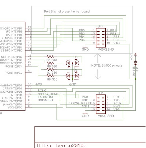
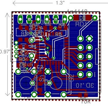
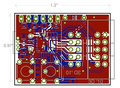
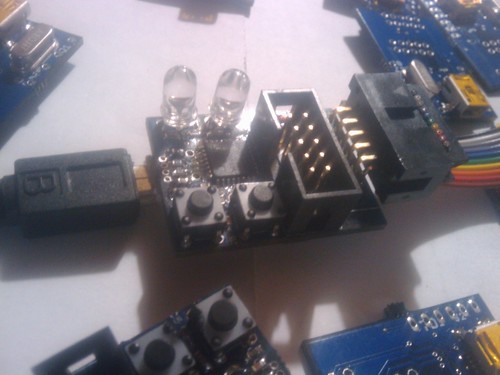
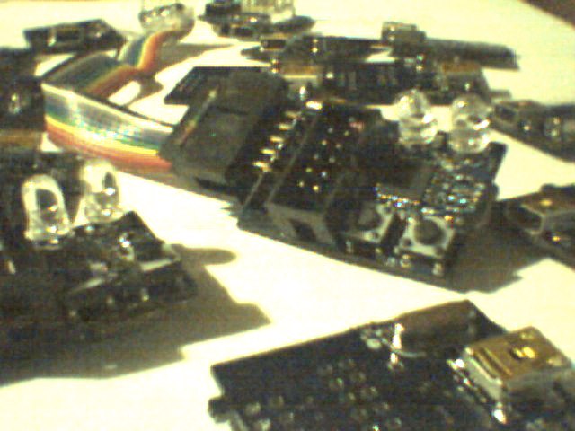
One of the benefits of having laens pcb order available is that I can test design changes iteratively and explore other possibilities. The benitos i am using in the induction this month are the result of three iterative changes based on the original Benito and a redesign done by Monty Goodson a few years back. They (the benito2010d) will be the last of the design to use the pinouts of the origional benito. Fot the end users the biggest change will be that the cable will be a mini-b like the one used on the teensy.

I am not entirely convinced that the mini-b is the right decision but the full sized b uses a lot of board real estate. The other changes on the board come from things that I did and did not like in the previous iterations.This board uses a few through hole parts where the previous versions used surface mount most noticeably for the leds and the switches. I also find that solder mask is not something to be left off of a board.

The next iteration will abandon the original benito pin-out in favor of the stk500 style pin-outs.

There will be two versions of this board available.

The e1 which will be primarily for the inductions and the e2 which will replace the benito pcb on the tempus dictum site.  I will update the parts list shortly along with the other parts of the site with the new design once the next board order goes through.