by on reference


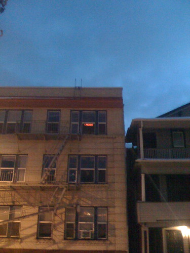
War on Christmas Lights from Donald Delmar Davis on Vimeo.

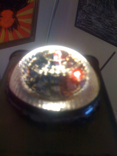
Last year I cast a series of led arrays for thing-a-day but hadnt wired them up. With this in mind I ordered some hc595s in the last group order but the snow canceled the meeting.

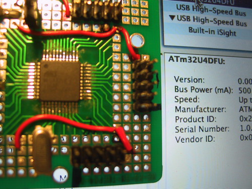
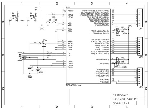
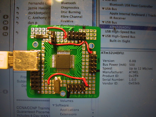
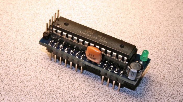
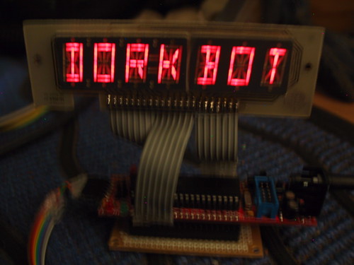
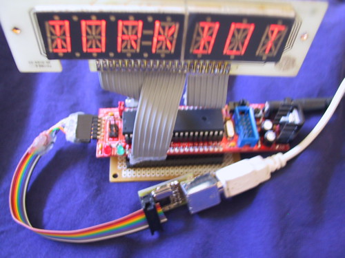
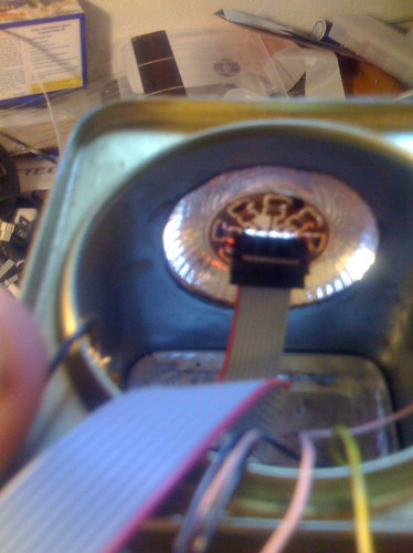
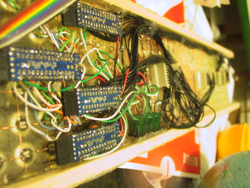
I have been thinking about using the avr to drive the arrays directly and control them using i2c. I hacked 4 dorkboards by cutting the traces for pins 5-12 on the top of the board and soldering 220 ohm resistors on the other side. This gives a one chip solution which does not require a constant refresh or other attention.

/*
 Simple 4 node array of leds (8x8).
 */
#include <Wire.h>

int node=0; /* CHANGE THIS BASED ON POSITION OF ARRAY */

volatile int twi_group_offset=128;

volatile int colpins[]={//12,11,10,9,8,7,6,5};
5,6,7,8,9,10,11,12};
volatile int rowpins[]={
17,16,15,14,13,4,3,2};
//2,3,4,13,14,15,16,17};

volatile unsigned long int myTics;

unsigned char pixels[]={0x3E, 0x51, 0x49, 0x45, 0x3E,0,0,node,
0x00, 0x42, 0x7F, 0x40, 0x00,0,1,1,
0x42, 0x61, 0x51, 0x49, 0x46,0,2,2,
0x21, 0x41, 0x45, 0x4B, 0x31,0,3,3
};

void setup()                    // run once, when the sketch starts
{

	int i;
	myTics=millis();
	for(i=0;i<8;i++){
		pinMode(rowpins[i],OUTPUT);
		digitalWrite(rowpins[i],LOW);
		pinMode(colpins[i],OUTPUT);
		digitalWrite(colpins[i],HIGH);
	}    // sets the digital pin as output
	if (node==0) {
		Wire.begin();
		Serial.begin(19200);
		updateSlaveNodes();
	} else {
		Wire.begin(node+twi_group_offset);
		Wire.onReceive(updatePixels); // register event
	}
}

void loop()                    //move most of this into a timer loop.
{
	int r,c;
	int lastcolpin=colpins[0];
	for (c=0;c<8;c++){
		lastcolpin=colpins[c];
		for(r=0;r<8;r++){
			if ((pixels[c]>>r)&0x01){
				//if ((!r)||((7-c)==r)||(c==r)){
				digitalWrite(rowpins[r], HIGH);
			} else {
				digitalWrite(rowpins[r], LOW);
			}
		}
		digitalWrite(colpins[c], LOW);
		if (node==0) {
			updateSlaveNodes();
		} else {
			//delayMicroseconds(1500); //
			delay(3);
		}
		digitalWrite(lastcolpin, HIGH);
	}
}

void updateSlaveNodes() {
	int slavenode, row, pixel8;
	pixel8=8;
	for (slavenode=1;slavenode<4;slavenode++){
		Wire.beginTransmission(slavenode+twi_group_offset);
		for (row=0;row<8;row++) {
			Wire.send(pixels[pixel8++]);
		}
		Wire.endTransmission();
	};
}

// function that executes whenever data is received from master
// this function is registered as an event, see setup()
void updatePixels(int howMany)
{ int r=0;
	while(Wire.available()) //
	{
		pixels[r++] = Wire.receive(); // receive byte as a character
	}
}


The next step is to move the actual refresh into a timer routine so that the body of code for the main node can focus on content.

/*------------------------------------------------------------ xmas timer array
 *
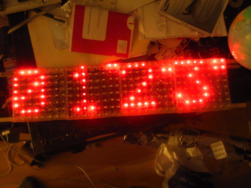
 * This is the program for a 4x8x8 led display using a processor for each segment
 * To program the different nodes set the node variable below. Node 0 is the
 * master node which keeps the pixel memory for the remaining nodes.
 *
 * The master node takes its memory and sends updates to each of the other segments
 * via the i2c buss using the Wire library.
 *
 * Each node takes its 8byte array of data and strobes it onto the display using
 * the 8 bit timer2 overflow interrupt.
 *
 * The first 7 characters are loaded into the display memory using the
 * loadCharacters function. The array is then shifted to the left in the main loop
 * with the next character being loaded a collumn at a time.
 *
 * The character data and the bitmap for the 5x7 array are stored in program
 * memory.
 *
 * Since interrupts are used all of the globals are marked as volatile.
 *
 * CopyLeft 2008 Donald Delmar Davis, Tempus Dictum, Inc.
 * This is free software (GPL)
 */
#include <Wire.h>
#include <avr/interrupt.h>
#include <avr/io.h>
#include <avr/pgmspace.h>

#define FREEK 180

int node=0; /* CHANGE THIS BASED ON POSITION OF ARRAY */

unsigned char PROGMEM Font5x7[] = {
0x00, 0x00, 0x00, 0x00, 0x00,// (space)
0x00, 0x00, 0x5F, 0x00, 0x00,// !
0x00, 0x07, 0x00, 0x07, 0x00,// "
0x14, 0x7F, 0x14, 0x7F, 0x14,// #
0x24, 0x2A, 0x7F, 0x2A, 0x12,// $
0x23, 0x13, 0x08, 0x64, 0x62,// %
0x36, 0x49, 0x55, 0x22, 0x50,// &
0x00, 0x05, 0x03, 0x00, 0x00,// '
0x00, 0x1C, 0x22, 0x41, 0x00,// (
0x00, 0x41, 0x22, 0x1C, 0x00,// )
0x08, 0x2A, 0x1C, 0x2A, 0x08,// *
0x08, 0x08, 0x3E, 0x08, 0x08,// +
0x00, 0x50, 0x30, 0x00, 0x00,// ,
0x08, 0x08, 0x08, 0x08, 0x08,// -
0x00, 0x60, 0x60, 0x00, 0x00,// .
0x20, 0x10, 0x08, 0x04, 0x02,// /
0x3E, 0x51, 0x49, 0x45, 0x3E,// 0
0x00, 0x42, 0x7F, 0x40, 0x00,// 1
0x42, 0x61, 0x51, 0x49, 0x46,// 2
0x21, 0x41, 0x45, 0x4B, 0x31,// 3
0x18, 0x14, 0x12, 0x7F, 0x10,// 4
0x27, 0x45, 0x45, 0x45, 0x39,// 5
0x3C, 0x4A, 0x49, 0x49, 0x30,// 6
0x01, 0x71, 0x09, 0x05, 0x03,// 7
0x36, 0x49, 0x49, 0x49, 0x36,// 8
0x06, 0x49, 0x49, 0x29, 0x1E,// 9
0x00, 0x36, 0x36, 0x00, 0x00,// :
0x00, 0x56, 0x36, 0x00, 0x00,// ;
0x00, 0x08, 0x14, 0x22, 0x41,// <
0x14, 0x14, 0x14, 0x14, 0x14,// =
0x41, 0x22, 0x14, 0x08, 0x00,// >
0x02, 0x01, 0x51, 0x09, 0x06,//
0x32, 0x49, 0x79, 0x41, 0x3E,// @
0x7E, 0x11, 0x11, 0x11, 0x7E,// A
0x7F, 0x49, 0x49, 0x49, 0x36,// B
0x3E, 0x41, 0x41, 0x41, 0x22,// C
0x7F, 0x41, 0x41, 0x22, 0x1C,// D
0x7F, 0x49, 0x49, 0x49, 0x41,// E
0x7F, 0x09, 0x09, 0x01, 0x01,// F
0x3E, 0x41, 0x41, 0x51, 0x32,// G
0x7F, 0x08, 0x08, 0x08, 0x7F,// H
0x00, 0x41, 0x7F, 0x41, 0x00,// I
0x20, 0x40, 0x41, 0x3F, 0x01,// J
0x7F, 0x08, 0x14, 0x22, 0x41,// K
0x7F, 0x40, 0x40, 0x40, 0x40,// L
0x7F, 0x02, 0x04, 0x02, 0x7F,// M
0x7F, 0x04, 0x08, 0x10, 0x7F,// N
0x3E, 0x41, 0x41, 0x41, 0x3E,// O
0x7F, 0x09, 0x09, 0x09, 0x06,// P
0x3E, 0x41, 0x51, 0x21, 0x5E,// Q
0x7F, 0x09, 0x19, 0x29, 0x46,// R
0x46, 0x49, 0x49, 0x49, 0x31,// S
0x01, 0x01, 0x7F, 0x01, 0x01,// T
0x3F, 0x40, 0x40, 0x40, 0x3F,// U
0x1F, 0x20, 0x40, 0x20, 0x1F,// V
0x7F, 0x20, 0x18, 0x20, 0x7F,// W
0x63, 0x14, 0x08, 0x14, 0x63,// X
0x03, 0x04, 0x78, 0x04, 0x03,// Y
0x61, 0x51, 0x49, 0x45, 0x43,// Z
0x00, 0x00, 0x7F, 0x41, 0x41,// [
0x02, 0x04, 0x08, 0x10, 0x20,// "\"
0x41, 0x41, 0x7F, 0x00, 0x00,// ]
0x04, 0x02, 0x01, 0x02, 0x04,// ^
0x40, 0x40, 0x40, 0x40, 0x40,// _
0x00, 0x01, 0x02, 0x04, 0x00,// `
0x20, 0x54, 0x54, 0x54, 0x78,// a
0x7F, 0x48, 0x44, 0x44, 0x38,// b
0x38, 0x44, 0x44, 0x44, 0x20,// c
0x38, 0x44, 0x44, 0x48, 0x7F,// d
0x38, 0x54, 0x54, 0x54, 0x18,// e
0x08, 0x7E, 0x09, 0x01, 0x02,// f
0x08, 0x14, 0x54, 0x54, 0x3C,// g
0x7F, 0x08, 0x04, 0x04, 0x78,// h
0x00, 0x44, 0x7D, 0x40, 0x00,// i
0x20, 0x40, 0x44, 0x3D, 0x00,// j
0x00, 0x7F, 0x10, 0x28, 0x44,// k
0x00, 0x41, 0x7F, 0x40, 0x00,// l
0x7C, 0x04, 0x18, 0x04, 0x78,// m
0x7C, 0x08, 0x04, 0x04, 0x78,// n
0x38, 0x44, 0x44, 0x44, 0x38,// o
0x7C, 0x14, 0x14, 0x14, 0x08,// p
0x08, 0x14, 0x14, 0x18, 0x7C,// q
0x7C, 0x08, 0x04, 0x04, 0x08,// r
0x48, 0x54, 0x54, 0x54, 0x20,// s
0x04, 0x3F, 0x44, 0x40, 0x20,// t
0x3C, 0x40, 0x40, 0x20, 0x7C,// u
0x1C, 0x20, 0x40, 0x20, 0x1C,// v
0x3C, 0x40, 0x30, 0x40, 0x3C,// w
0x44, 0x28, 0x10, 0x28, 0x44,// x
0x0C, 0x50, 0x50, 0x50, 0x3C,// y
0x44, 0x64, 0x54, 0x4C, 0x44,// z
0x00, 0x08, 0x36, 0x41, 0x00,// {
0x00, 0x00, 0x7F, 0x00, 0x00,// |
0x00, 0x41, 0x36, 0x08, 0x00,// }
0x08, 0x08, 0x2A, 0x1C, 0x08,// ->
0x08, 0x1C, 0x2A, 0x08, 0x08 // <-
};

unsigned char PROGMEM banner[] = "Happy Holidays!!! Merry Christmas!!! May every man with \"Merry Christmas\" on his lips be boiled in his own blood pudding with a steak of holly driven through his heart! Christmas! BAH! HUMBUG!!!";

volatile int twi_group_offset=128;
volatile int colpins[]={5,6,7,8,9,10,11,12};
volatile int rowpins[]={17,16,15,14,13,4,3,2};

volatile unsigned long int myTics; //counter for timer interrupt.

volatile unsigned char pixels[]={
0x3E, 0x51, 0x49, 0x45, 0x3E,0,0,node,
0x00, 0x42, 0x7F, 0x40, 0x00,0,0,1,
0x42, 0x61, 0x51, 0x49, 0x46,0,0,2,
0x21, 0x41, 0x45, 0x4B, 0x31,0,0,3,
0x00, 0x00, 0x00, 0x00, 0,0,0,0}; //pixel buffer rounded out to another 8 bytes

volatile unsigned int cursorpos=0;
volatile unsigned int charcursor=0;
volatile unsigned int currentcol;
volatile unsigned int charmod;
volatile unsigned char currentchar;
volatile unsigned int currentcharoffset;

/*---------------------------------------------------------------------setup()
 * initialize timer2
 * setup the i/o pins (initialized with everything off);
 * Initialize the i2c buss;
 * if master node then load initial characters into display.
 */
void setup()                    // run once, when the sketch starts
{

    int i;
    currentcol=0;

    /*------------ setting up timer two. ----------------*/
    TCCR2A = 0;                           // normal mode
    TCCR2B = 1<<CS22 | 1<<CS21 | 0<<CS20; // clock selection
    TIMSK2 |= 1<<TOIE2;          // enable overflow interupt
    TCNT2=FREEK;                 // adjustment of period
    ASSR=0; // paranoid
    myTics=0;                    // counter for delays
    sei();                       // enable interrupts

   for(i=0;i<8;i++){
		pinMode(rowpins[i],OUTPUT);
		digitalWrite(rowpins[i],LOW);
		pinMode(colpins[i],OUTPUT);
		digitalWrite(colpins[i],HIGH);
    }

    if (node==0) {            // master node
		Wire.begin();
		Serial.begin(19200);
                loadCharacters();
		updateSlaveNodes();
    } else {
		Wire.begin(node+twi_group_offset);
		Wire.onReceive(updatePixels); // register event
    }
}

/*------------------------------------------------------------ISR(TIMER2_OVF_vect)
 * loads the next collumn into the led array
 *
 */
ISR(TIMER2_OVF_vect) {
int r;
  digitalWrite(colpins[currentcol], HIGH); //turn off the last column.

  if (++currentcol > 7) {
    currentcol=0;
  }
  for(r=0;r<8;r++){
	if ((pixels[currentcol]>>r)&0x01){
		digitalWrite(rowpins[r], HIGH);
	} else {
		digitalWrite(rowpins[r], LOW);
	}
  }
  digitalWrite(colpins[currentcol], LOW);
  myTics++;
  TCNT2 = FREEK;


};

/*--------------------------------------------------------------loadCharacters()
 * load the initial characters into the pixel buffer
 */
void loadCharacters(){
  int ch,i,j;
  cursorpos=0;
  for (charcursor=0;charcursor<7;charcursor++) {
    ch=pgm_read_byte_near(banner+charcursor);
    j= (ch-32) & 0x000000ff;
    j = j*5;
   for (charmod=0;charmod<5;charmod++){
      pixels[cursorpos++]=pgm_read_byte_near(Font5x7+j+charmod);
    }
  }

}

/*------------------------------------------------------------updateSlaveNodes()
 *  send the pixel data to the slave nodes.
 */

void updateSlaveNodes() {
  int slavenode, row, pixel8;

  if (node==0) {
	pixel8=8;
	for (slavenode=1;slavenode<4;slavenode++){
		Wire.beginTransmission(slavenode+twi_group_offset);
		for (row=0;row<8;row++) {
			Wire.send(pixels[pixel8++]);
		}
		Wire.endTransmission();
	};
  }
}
/*------------------------------------------------------------------udatePixels()
 * recieve the pixel data from the master node.
 * executes whenever data is received from master
 * this function is registered as an event, see setup()
 */
void updatePixels(int ignored)
{ int r=0;
	while(Wire.available()) //
	{
		pixels[r++] = Wire.receive(); // receive byte as a character
	}
}

/*-------------------------------------------------------------------------loop()
 *
 */
void loop()
{int c;

 //int head=pixels[0];
 updateSlaveNodes();

 for (c=1;c<35;c++) {
   pixels[c-1]=pixels[c];
 }


  if (charmod==5) {//get next char
    charcursor++;
    charmod=0;
    currentchar=pgm_read_byte_near(banner+charcursor);
    if (currentchar=='\0'){
       currentchar=pgm_read_byte_near(banner);
       charcursor=0;
    }
    currentcharoffset = (currentchar-32) & 0x000000ff;
    currentcharoffset = currentcharoffset*5;
  }

  pixels[34]=pgm_read_byte_near(Font5x7+currentcharoffset+charmod);
  charmod++;

 while (myTics<90) ; myTics=0L; //wait a few hundred millisecconds

}


http://www.dorkbotpdx.org/files/xmastimer-081225b.zip

by on Avr Development

Mega 32 U4

While I am wrangling with the appropriate board design, I needed to get started working with the underlying software so I ran up one of the six samples I was able to get from Cascade on a tqfp adapter from measure explorer.

Schematic For Test Board

The AtMega32U4 http://www.atmel.com/dyn/products/product_card.asp?part_id=4317 is the midrange model in the atmel usb chipset. It follows a new standard naming convention that atmel is adapting U for Usb 4 is for the 40 pins 32k, there is another 32K part the U6 which has the same pinouts as the 90usb646/647/1286/1287. The U4 does not have a legacy pinout however the q1000 price for this board is around $2 which makes it a very powerful chip for the money.

Dfu-Programmer.

There is a recent release of dfu-programmer (0.4.6) but it seems that they havent read the atmel doc on the signatures for the dfu recently. http://www.atmel.com/dyn/resources/prod_documents/doc7618.pdf recently.

I need to check the memory and eeprom sizes against the datasheets for the parts. However the table in arguments.c should have the following entries; added new parts, corrected 64x and 82 signatures. (I will resubmit this patch).

/* ----- target specific structures ----------------------------------------- */
/*  { "name",         value,            ,device_type, chipID,VID   , MemSize,FPSize,abt,ifclass,eepgsz,eepmemsz} */
static struct target_mapping_structure target_map[] = {
    { "at89c51snd1c", tar_at89c51snd1c, device_8051, 0x2FFF, 0x03eb, 0x10000, 128, false, true,  0,   0      },
    { "at89c5130",    tar_at89c5130,    device_8051, 0x2FFD, 0x03eb, 0x04000, 128, false, true,  128, 0x03FF },
    { "at89c5131",    tar_at89c5131,    device_8051, 0x2FFD, 0x03eb, 0x08000, 128, false, true,  128, 0x03FF },
    { "at89c5132",    tar_at89c5132,    device_8051, 0x2FFF, 0x03eb, 0x10000, 128, false, true,  0,   0      },
    { "at90usb1287",  tar_at90usb1287,  device_AVR,  0x2FFB, 0x03eb, 0x1F000, 128, true,  false, 128, 0x0FFF },
    { "at90usb1286",  tar_at90usb1286,  device_AVR,  0x2FFB, 0x03eb, 0x1F000, 128, true,  false, 128, 0x0FFF },
    { "at90usb647",   tar_at90usb647,   device_AVR,  0x2FF9, 0x03eb, 0x0F000, 128, true,  false, 128, 0x07FF },
    { "at90usb646",   tar_at90usb646,   device_AVR,  0x2FF9, 0x03eb, 0x0F000, 128, true,  false, 128, 0x07FF },
    { "atmega32U6",   tar_atMega32u6,   device_AVR,  0x2FFB, 0x03eb, 0x07000, 128, true,  false, 128, 0x03FF },
    { "atmega32U4",   tar_atMega32u4,   device_AVR,  0x2FF4, 0x03eb, 0x07000, 128, true,  false, 128, 0x03FF },
    { "atmega16U4",   tar_atMega16u4,   device_AVR,  0x2FF3, 0x03eb, 0x03000, 128, true,  false, 128, 0x01FF },
    { "at90usb162",   tar_at90usb162,   device_AVR,  0x2FFA, 0x03eb, 0x03000, 128, true,  false, 128, 0x01FF },
    { "at90usb82",    tar_at90usb82,    device_AVR,  0x2FF7, 0x03eb, 0x01000, 128, true,  false, 128, 0x01FF },
    { NULL }
};

Then we test.

static
dfu-programmer atMega32U4 get bootloader-version --debug 20
     target: atMega32U4
    chip_id: 0x2ff4
  vendor_id: 0x03eb
    command: get
      quiet: false
      debug: 20
device_type: AVR
------ command specific below ------
       name: 0

Bootloader Version: 0x00 (0)

(after reading the datasheets for the 3 classes of avr usb chips and looking at the way that the avr-gcc library calls the cpu names there are some changes to the above that I will post later.)

Next up some code.

Tried running up the midiGate software that I wrote last week and found my first bug for the chip in avr-libc

UBRR1 is redefined in iom32u4.h

#define UBRR1 _SFR_MEM16(0xCC)

#define UBRR1L _SFR_MEM8(0xCC)
#define UBRR0 0
#define UBRR1 1
...

Which results in lvalue errors errors when trying to set the register to a given value. Setting the bit values as in some of the other registers seems to resolve this issue.

#define UBRR1 _SFR_MEM16(0xCC)

#define UBRR1L _SFR_MEM8(0xCC)
#define UBRR_0 0
#define UBRR_1 1
#define UBRR_2 2
#define UBRR_3 3
#define UBRR_4 4
#define UBRR_5 5
#define UBRR_6 6
#define UBRR_7 7

#define UBRR1H _SFR_MEM8(0xCD)
#define UBRR_8 0
#define UBRR_9 1
#define UBRR_10 2
#define UBRR_11 3

This is a pretty braindead error so I am sure that its been resolved by now. I need to see if it is fixed in 1.6.3 or the current release candidate (since AvrMacPack is out of sync and has 1.6.2) And yes this is the case.

We have a device!!!

Fix(ing) it!

Both of these issues were easy enough to fix within the source of the utilities but to make it possible for everyone else to use the new chips some body needs to Fix it! So I went about looking up the chain to get these issues resolved over the long run.

Dfu Programmer.

dfu-programmer is a source forge project so I logged an error through the sourceforge project page. https://sourceforge.net/tracker2/?atid=767783&group_id=147246&func=browse A new release has been made (0.5.0) which resolves the issue above.

Avr-Libc

Since avr-libc is a savanaha project and so making bug requests is a little different. http://savannah.nongnu.org/bugs/?group=avr-libc Fortunately (sort of) I had already been around the buggier parts of the release in question (1.6.2) when I first ran up the at90usb647. When Eric Weddington released the June rev of WinAvr (with avr-libc 1.6.3) I thought I had seen the last of it as obdev released the coresponding AvrMacPack. The bug noted above was fixed in 1.6.3 and I was able to verify that using my windows vmware session. For some reason this was not the case and AvrMacPack went out with the buggy (for this new chip anyway) libc. I filed a bug report with obdev and followed up with Christian from obdev and Eric until the version descrepency was resolved. The new version of WinAvr just came out and I am waiting to verify that the AvrMacPack version matches WinAvr.

If you are running linux plan on building from source and patching as in the script kept current at avrfreaks (you will need to log in) . http://www.avrfreaks.net/index.php?name=PNphpBB2&file=viewtopic&t=42631&start=0&postdays=0&postorder=asc&highlight= This script has not been updated for the latest winavr but it should at least give you a version above 1.6.2.

by on Dorkbot


I finally got a chance to wire up the first of my ATMega32U4 samples (see atmel doc7766). Like all of atmel’s usb chips it comes up as a bootloader. Now we get to go through the list of things that are probably broken (starting with dfu-programmer which I already know from fixing it for the at90usb647 is broken).

  • dfu-programmer
  • the bootloader itself (as was the case with the 90usb647)
  • avr-gcc
  • avr-libc
  • LUFA (soon to be formarly known as MyUSB)


Let the games begin…

by on Dorkbot

http://farm4.static.flickr.com/3208/3043303516_20722aebfd.jpg

As a part of the ongoing Arduino Cult Induction workshop series, this month we will be focusing on sound.

In particular I will be going over creating sound using the Arduino’s built in Pulse Width Modulation (PWM) and Direct Digital Synthesis using resistive ladders. We will investigate using the Piezo element
as both a simple speaker and an input trigger. We will review the Musical Instrument Digital Interface (MIDI) from a hardware and software perspective, and look at a couple of useful integrated
circuits (the lm324 and the lm368).

The workshop will cost $25 and participants will recieve a complete midi interface board for the dorkboard/arduino and a piezo element which will be used to create a midi drum trigger.
Participants will also take with them parts for an r2r ladder, an op amp and an audio amp capable of driving small speakers or headphones.

Participants should leave the workshop with a better understanding of how micro-controllers such as the Arduino can be used to create and control sound, they should have built at least one working musical controller and they should have the foundations for several sound related projects.

Please bring your dorkboard, rbba, or other arduino compatible board, a soldering iron or breadboard, and a laptop.

The workshop will be held at PNCA (NW 12th and Johnson) in room 205 from 1-5pm on Sunday, November 30.

To reserve a space you can paypal the workshop fee to cult@tempusdictum.com and you can feel free to email me with any questions.

The Arduino Cult Induction series of workshops are Sponsored by [http://www.tempusdictum.com/ Tempus Dictum, Inc]. in support of [http://www.dorkbotpdx.org DorkbotPDX]. (graphic by [http://www.noisybox.net Jason Plumb] )

by on Dorkbot

I am trying to digest this document.

http://www.usb.org/developers/devclass_docs/midi10.pdf

USB encapsulates midi data into 4 byte chunks and adds the notion of virtual cables.
The first byte in the packet is the cable number and something called the Code Index Number. The remaining 3 bytes are either midi or padding depending on the packet.

Most of the relevant midi status commands have a corresponding Code Index Number.

USB Midi Codes with 1to1 Midi Status Mapping
c=virtual cable,n=midi channel
CIN Status Bytes Description
0xc8 0x8n 2 Note ON
0xc9 0x9n 2 Note OFF
0xcA 0xAn 2 Key Pressure
0xcB 0xBn 2 Control Change
0xcC 0xCn 1 Program Change
0xcD 0xDn 1 Channel Pressure
0xcE 0xEx 2 Pitch Wheel

The rest of it is a mess of what to do with the odd sysex bytes. To pass the input stream to midi should look something like this.

/* Select the Stream Out Endpoint */
Endpoint_SelectEndpoint(MIDI_STREAM_OUT_EPNUM);

if (Endpoint_ReadWriteAllowed())
{
	/* Read the recieved data endpoint into the transmission buffer */
	while (Endpoint_BytesInEndpoint())
	{   cin=Endpoint_Read_Byte();
		midibyte[0]=Endpoint_Read_Byte(); // should probably do some sort of checking here.
		midibyte[1]=Endpoint_Read_Byte(); // should probably do some sort of checking here.
		midibyte[2]=Endpoint_Read_Byte(); // should probably do some sort of checking here.
		i=0;
		switch (cin&0x0F) { //strip off cable data.
			case CIN_3BYTE_SYSTEM_COMMON:
			case CIN_SYSEX_ENDS_IN_THREE:
			case CIN_NOTE_ON:
			case CIN_NOTE_OFF:
			case CIN_PRESSURE:
			case CIN_SYSEX_CONTINUES:
			case CIN_PITCH_WHEEL:
			case CIN_CONTROL_CHANGE:
				while (!((BUFF_STATICSIZE - Rx_Buffer.Elements)));
				Buffer_StoreElement(&Rx_Buffer,midibyte[i++]);
			case CIN_SYSEX_ENDS_IN_TWO:
			case CIN_2BYTE_SYSTEM_COMMON:
			case CIN_PROGRAM_CHANGE:
			case CIN_CHANNEL_PRESSURE:
				while (!((BUFF_STATICSIZE - Rx_Buffer.Elements)));
				Buffer_StoreElement(&Rx_Buffer,midibyte[i++]);
			case CIN_SYSEX_ENDS_IN_ONE:
			case CIN_SYSTEM_1BYTE:
				while (!((BUFF_STATICSIZE - Rx_Buffer.Elements)));
				Buffer_StoreElement(&Rx_Buffer,midibyte[i++]);
			case CIN_RESERVED_FUNCTION_CODES:
			case CIN_RESERVED_CABLE_EVENTS:
				break;
		}
		Flash_RXD(); // do the pov thing
	}

	/* Clear the endpoint buffer */
	Endpoint_ClearCurrentBank();
}


In other words since the midi data is complete in the packets. You just need to determine how many of the 4 bytes to send and strip off the cable information.

Going the other way is a little more convoluted.

void ParseMidiByte(const uint8_t theByte) {
    if (theByte&0x80) {
		thePacketIndex=0;
		switch (theByte&0xF0) {
			case MIDI_STATUS_NOTE_ON:
			case MIDI_STATUS_NOTE_OFF:
			case MIDI_STATUS_PRESSURE:
			case MIDI_STATUS_CONTROL_CHANGE:
			case MIDI_STATUS_PITCH_WHEEL:
				thePacket[thePacketIndex++] = theCable|(theByte>>4);
				thePacket[thePacketIndex++] = theByte;
				theMidiState = midi_state_needs_2bytes;
				break;
			case MIDI_STATUS_PROGRAM_CHANGE:
			case MIDI_STATUS_CHANNEL_PRESSURE:
				thePacket[thePacketIndex++] = theCable|(theByte>>4);
				thePacket[thePacketIndex++] = theByte;
				theMidiState = midi_state_needs_1byte;
				break;
			case MIDI_STATUS_SYSTEM:
				if (theByte & 0x08) {// System Real Time Messages
					Endpoint_Write_Byte(theCable|CIN_SYSTEM_1BYTE);
					Endpoint_Write_Byte(theByte);
					Endpoint_Write_Byte(0);
					Endpoint_Write_Byte(0);
					Endpoint_ClearCurrentBank();
				} else if (theByte == 0xF0) {
					thePacket[thePacketIndex++] = theCable|CIN_SYSTEM_1BYTE;
					thePacket[thePacketIndex++] = theByte;
					theMidiState=midi_state_in_sysex;
				} else if (theByte == 0xF3) {//Song Select
					thePacket[thePacketIndex++] = theCable|CIN_2BYTE_SYSTEM_COMMON;
					thePacket[thePacketIndex++] = theByte;
					theMidiState=midi_state_needs_1byte;
				} else if (theByte == 0xF2) { //Song Position Pointer
					thePacket[thePacketIndex++] = theCable|CIN_3BYTE_SYSTEM_COMMON;
					thePacket[thePacketIndex++] = theByte;
					theMidiState=midi_state_needs_2bytes;
				} else if (theByte == MIDI_EOX) {
					if (thePacketIndex==3) {
						thePacket[0]=theCable|CIN_SYSEX_ENDS_IN_THREE;
					} else if (thePacketIndex==2) {
						thePacket[0]=theCable|CIN_SYSEX_ENDS_IN_TWO;
					} else {
						thePacket[0]=theCable|CIN_SYSEX_ENDS_IN_ONE;
					}
					thePacket[thePacketIndex]=0xF7;
					theMidiState=midi_state_idle;
					thePacketIndex=4;
				} else {
					// undefined -- bin it.
					theMidiState=midi_state_idle;
				}

		}
	} else {
		switch(theMidiState) {
			case midi_state_needs_2bytes:
				thePacket[thePacketIndex++]=theByte;
				theMidiState = midi_state_needs_1byte;
				break;
			case midi_state_needs_1byte:
				thePacket[thePacketIndex++]=theByte;
				thePacketIndex=4;
				theMidiState = midi_state_idle;
				break; //this was missing in the first post
			case midi_state_in_sysex:
				thePacket[thePacketIndex++]=theByte;
				break;
		}
		if(thePacketIndex==4){
			while (!(Endpoint_ReadWriteAllowed()));
			Endpoint_Write_Byte(thePacket[0]);
			Endpoint_Write_Byte(thePacket[1]);
			Endpoint_Write_Byte(thePacket[2]);
			Endpoint_Write_Byte(thePacket[3]);
			Endpoint_ClearCurrentBank();
			thePacket[0]=thePacket[1]=thePacket[2]=thePacket[3]=0;
			thePacketIndex=0;
		}

	}


}

by on Dorkbot

Wanna dorkboard but afraid of surface mount?

Brian Riley at Wulfden will sell you a stripped down dorkboard kit with the reset pullup resister and the programming jumper ALREADY SOLDERED! and for another 6 bucks you can build a nifty flashlight!

http://www.1strecon.org/TheShoppe/flashlight/index.shtml


Schematic for the flashlight kit.

by on Dorkbot

Using the new features of arduino 12.

There is much that is new in the new arduino. Most of it in the user libraries and all of it good. My favorite is the addition of the ability to specify a different programmer as long as its avrdude approved.

boards.txt and programmers.txt

If you select the boards on my Arduino setup it will look very different than the stock Arduino.

In the arduino software folder you will find the boards.txt in a folder under hardware. To add a board you copy one of the existing entries and modify it to fit your board. The sample I use here is from the Sanguino, a mega 644P based arduino “core” (see www.sanguino.cc for instuctions on installing this core with arduino 12).

##############################################################

sanguino.name=Sanguino W/ bootloader

sanguino.upload.using=bootloader
sanguino.upload.protocol=stk500
sanguino.upload.maximum_size=63488
sanguino.upload.speed=38400

sanguino.bootloader.low_fuses=0xFF
sanguino.bootloader.high_fuses=0xDC
sanguino.bootloader.extended_fuses=0xFD
sanguino.bootloader.path=atmega644
sanguino.bootloader.file=ATmegaBOOT_644.hex
sanguino.bootloader.unlock_bits=0x3F
sanguino.bootloader.lock_bits=0x0F
sanguino.build.mcu=atmega644P
sanguino.build.f_cpu=16000000L
sanguino.build.core=sanguino
sanguino.verbose=false

I have a maze following mouse that I built a year and a half ago that uses the atMega644V which is very similar to the 644P, after looking at the underlying code and seeing that it is written well enough to adjust to the differences between the two chips (mostly an extra serial port), I was pretty sure that the code would compile and run on the older chip. So I modified the board entry to match my board.

##############################################################

megmouse.name=MegMouse W/ avrispmkII

megmouse.upload.using=avrispmk2
megmouse.upload.maximum_size=63488
megmouse.upload.speed=38400

megmouse.bootloader.low_fuses=0xFF
megmouse.bootloader.high_fuses=0xDC
megmouse.bootloader.extended_fuses=0xFD
megmouse.bootloader.path=atmega644
megmouse.bootloader.file=ATmegaBOOT_644.hex
megmouse.bootloader.unlock_bits=0x3F
megmouse.bootloader.lock_bits=0x0F
megmouse.build.mcu=atmega644
megmouse.build.f_cpu=8000000L
megmouse.build.core=sanguino
megmouse.verbose=false

The first chunk in each entry is the category or class of the board and groups the text entries together. I wont pretend to be a java programmer and understand how it works just that the above works.

The important changes needed were in the .build lines where I changed the mcu, the clock speed and the core (location of the core source). These are used to compile the program with avr-gcc.

The other noticable change is the .upload.using line which is new in arduino 12. (see http://arduino.cc/en/Main/ReleaseNotes)

(If you can find the the preferences.txt you will see that this is usually set to bootloader.)

The value here coresponds to an entry in programmers.txt which was added in 10 to support burning bootloaders. My entry for the mark 2 looks like this.

avrispmk2.name=avrispmk2
avrispmk2.communication=usb
avrispmk2.protocol=stk500v2

To load the new board and programmer I quit out of arduino and start it up again. Now when I look at my boards I see the new entry in the menu. Selecting this board will compile arduino’s libraries using the new target. Selecting verify will compile your code. This code will give meg deamon eyes.

/*
 * evil MegMouse eyes
 */

int leftMotorFwdPin=11;
int rightMotorFwdPin=9;
int leftMotorBackPin=8;
int rightMotorBackPin=10;
int leftMotorPwmPin=12;
int rightMotorPwmPin=13;
int rightEyePin=14;
int leftEyePin=15;

void setup()                    // run once, when the sketch starts
{
  pinMode(leftMotorFwdPin, OUTPUT);      // sets the digital pin as output
  digitalWrite(leftMotorFwdPin, LOW);      // sets the digital pin as output
  pinMode(leftMotorBackPin, OUTPUT);      // sets the digital pin as output
  digitalWrite(leftMotorBackPin, LOW);      // sets the digital pin as output
  pinMode(rightMotorFwdPin, OUTPUT);      // sets the digital pin as output
  digitalWrite(rightMotorFwdPin, LOW);      // sets the digital pin as output
  pinMode(rightMotorBackPin, OUTPUT);      // sets the digital pin as output
  digitalWrite(rightMotorBackPin, LOW);      // sets the digital pin as output
  analogWrite(leftMotorPwmPin,0);             // turn motor pwm off.
  analogWrite(rightMotorPwmPin,0);
  analogWrite(leftEyePin,0);                       // turn led pwm off.
  analogWrite(rightEyePin,0);
}

void loop()                     // run over and over again
{ int i;
  for (i = 0; i < 254; i++){
  analogWrite(leftEyePin,i);
  analogWrite(rightEyePin,i);    // fade eyes to on
  delay(2);
  }
  for (i = 254; --i >= 0; ){
  analogWrite(leftEyePin,i);   //
  analogWrite(rightEyePin,i);    // fade them to off
  delay(2);
  }
}

And the upload button will pass the parameters from your modified programmers.txt to avrdude and use the external programmer rather than requiring a bootloader and a reset.

by on Dorkbot

For a while now I have wanted to check out the sanguino project (www.sanguino.cc) firsthand. I wanted to see this thing that I had tried half heartedly to work out a couple of times in the past year and a half (i.e. running the arduino code on the atmega 644) actually running. I also wanted to test the benito against a new board and I wanted to revive the “MegMouse” boards I did over a year ago to control a couple of maze solving robots.

So I went to the Wulfden FreeDuino Shop Wulfden FreeDuino Shop (www.wulfden.org/TheShoppe/freeduino/) for one of his new Sanguinos. I assembled it (more or less) in a few hours at a friends house last week but then didnt ge’t the cable made for it until yesterday.

In the mean time I downloaded arduino 12 and the new “core” provided byt the sanguino team. After adding the new section to the boards.txt like the documentation said to do I selected the new board from the tools menue. When you change boards the arduino compiles its libraries against the new processor. This is outside of the core and the new Servo library would not compile. It was an easy fix though adding the new processor to the code distinguishing the mega8 timer register names from the mega168. The next time I went back to the sanguino site a new version already addressed this issue. I suspect as the 328s become readily avaliable some of these issues will get resolved within the arduino team itself.

Finally I was able to build out the cable for the benito.

The pinouts for thos inquiring minds go like this.

I still havent gotten used to the idea that red is the right color for the debug leds (green is for power) so I put mine in wrong (the power led is also backwards so it doesnt glow) but once I changed the code led from pin 13 to pin 0 “blink” blinked.

Then I went to the first thing that I could find that required more pins to drive then the arduino had. I pulled an old led display out of the junk heap. There were 15 segments on 7 digits(22 pins).

/*
 * Bad coder no docs / copyleft here...
 */
#define NSEGMENTS 15
#define NDIGITS 7
#define BLANK 36
int ledPin = 0;
//                   a, b, c, d, e, f, g, h, j, k, l, m, n, p,dp
int SegmentPin[] = {30,31, 2, 7, 5, 1,28,25,29,27, 4, 6,26,24, 3};
int DigitPin[] = {15,16,17,18,21,20,19};
char charmap[][14]={
 //a,b,c,d,e,f,g,h,j,k,l,m,n,p
  {0,0,0,0,0,0,1,0,1,1,1,0,1,1}, //0
  {1,1,1,1,1,1,0,1,1,1,0,1,1,1}, //1
  {0,0,1,0,1,1,1,1,0,1,1,0,1,1}, //2
  {0,1,0,0,1,1,1,0,0,1,1,1,1,1}, //3
  {1,0,0,1,1,0,1,1,0,1,1,1,0,1}, //4
  {0,1,0,0,1,0,1,1,0,1,1,1,0,1}, //5
  {0,1,0,0,0,0,1,1,0,1,1,1,0,1}, //6
  {0,1,1,1,1,1,1,0,1,1,0,1,1,1}, //7
  {0,0,0,0,0,0,1,1,0,1,1,1,0,1}, //8
  {0,0,0,0,1,0,1,1,0,1,1,1,0,1}, //9
  {0,0,0,1,0,0,1,1,0,1,1,1,0,1}, //A
  {0,0,0,0,1,1,0,1,0,1,0,1,1,1}, //B
  {0,1,1,0,0,0,1,1,1,1,1,1,1,1}, //C
  {0,0,0,0,1,1,0,1,1,1,0,1,1,1}, //D
  {0,1,1,0,0,0,1,1,1,1,1,1,0,1}, //E
  {0,1,1,1,0,0,1,1,1,1,1,1,0,1}, //F
  {0,1,0,0,0,0,1,1,0,1,1,1,1,1}, //G
  {1,0,0,1,0,0,1,1,0,1,1,1,0,1}, //H
  {0,1,1,0,1,1,0,1,1,1,0,1,1,1}, //I
  {1,0,0,0,0,1,1,1,1,1,1,1,1,1}, //J
  {1,1,1,1,0,0,1,0,1,0,1,1,0,1}, //K
  {1,1,1,0,0,0,1,1,1,1,1,1,1,1}, //L
  {1,0,0,1,0,0,1,0,1,1,1,1,1,0}, //M
  {1,0,0,1,0,0,1,1,1,0,1,1,1,0}, //N
  {0,0,0,0,0,0,1,1,1,1,1,1,1,1}, //O
  {0,0,1,1,0,0,1,1,0,1,1,1,0,1}, //P
  {0,0,0,0,0,0,1,1,1,0,1,1,0,1}, //Q
  {0,0,1,1,0,0,1,1,0,0,1,1,0,1}, //R
  {0,1,0,0,1,0,1,1,0,0,1,1,0,1}, //S
  {0,1,1,1,1,1,0,1,1,1,0,1,1,1}, //T
  {1,0,0,0,0,0,1,1,1,1,1,1,1,1}, //U
  {1,1,1,1,0,0,1,0,1,1,1,0,1,1}, //V
  {1,0,0,1,0,0,1,1,1,0,1,0,1,1}, //W
  {1,1,1,1,1,1,1,0,1,0,1,0,1,0}, //X
  {1,1,1,1,1,1,1,0,1,1,0,1,1,0}, //Y
  {0,1,1,0,1,1,1,0,1,1,1,0,1,1}, //Z
  {1,1,1,1,1,1,1,1,1,1,1,1,1,1}, //
  {1,1,1,1,1,1,1,1,1,1,1,1,1,1}

};

char ascii2charmap (char ac) {
  if (ac>'z') return BLANK;
  if (ac>='a') return ((ac-'a')+10);

  if (ac>'Z') return BLANK;
  if (ac>='A') return ((ac-'A')+10);
  if (ac>'9') return BLANK;
  if (ac>='0') return (ac-'0');
}


void setup()                    // run once, when the sketch starts
{ int i;
 for (i=0;i<NSEGMENTS;i++) {
  pinMode(SegmentPin[i], OUTPUT);      // sets the digital pin as output
  digitalWrite(SegmentPin[i], HIGH);      // sets the digital pin as output
 }
 for (i=0;i<NDIGITS;i++) {
  pinMode(DigitPin[i], OUTPUT);      // sets the digital pin as output
  digitalWrite(DigitPin[i], HIGH);      // sets the digital pin as output
 }
  pinMode(ledPin, OUTPUT);      // sets the digital pin as output
}

void loop()                     // run over and over again
{ int d,i;
  char *string="Dorkbot";
  for (d=0;d<7;d++){
   for (i=0;i<14;i++) {
       digitalWrite(SegmentPin[i],charmap[ascii2charmap(string[d])][i]);
   }
   digitalWrite(DigitPin[d],HIGH);
   delay(5);
   digitalWrite(DigitPin[d],LOW);
 }

  //delay(100);                  // waits for a second

}

E Whah La.

by on Dorkbot


As it gets dark I find myself needing to get the blinking lights working on my bycycle. I am also reminded of the ever present need to find space where you don’t have to breath what you work with. Three days after casting the first set of lights the apartment still reeks.

I have some particularly thick copper on some particularly thin fiberglass that I would like to explore further (more pictures below).