Today I re-wrote a USB servo driver for the benito and reconstructed the periscope that I built last year for the quartz composer demo that I wrote in December.
A few people including myself have had some issues with their Benito’s where the programmer sets one light on constantly and the next thing that happens is the the mac will go comatose (or to the beach if you like spinney ball metaphores). Not a very confidence inspiring behavior. To make matters worse the behavior was completely inconsistent.
For the last batch of programmers I forced myself to upgrade the original source code to the current version of Dean Camera’s LUFA library (the library formerly known as MyUSB) and went about trying to figure it out. The first thing I “fixed” in the new code was to make the leds ping pong when the device was enumerating so I could tell the difference between enumeration and data.
Previously I had thought that the issue was at the host somewhere between the deadended rxtx library used by the arduino ide to talk to the devices and the equally deadended libusb used to find them.
Once I made this work I was seeing that in some cases the RX LED was constantly on (to verify this I swapped the led pins). Then I realized that when the arduino isn’t actually talking to the system the rx pin on the benito is tristated in other words it “float”s and whatever noise comes along is then data to be transmitted. In addition to leaving the lights on this flood of data gets sent to the usb subsystem to be read by the serial device when it it opened (I haven’t verified this completely but it certainly explains what the spinney ball is about).
There are a couple of things that could be done here. You could not transmit data unless dtr was present. Or you could enable the internal pullup which solves the issue. I filed this as a bug with Dean and the next rev of the USBtoSerial demo will have a pullup on the tx pin as well.
I suppose I need to show people how to upgrade their benitos. The new firmware and source are attached. (http://www.dorkbotpdx.org/files/Benito7g0109.tgz) If you have a troublesome Benito I will be happy to upgrade it at any of the upcoming meetings.
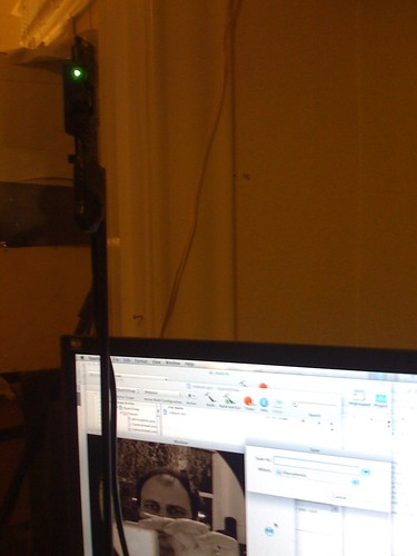
Yesterday I asked Greg Borenstein what he was using to do his really cool Arduino presentations to show the hardware alongside the code being used to program it. His answer suprised me. It was a simple Quartz Composition run using Composer. He used it to flip the views put out by his web cam so that they made sense from the users viewpoint. I have been seeing a lot of people using quartz composer to do testing and other cool graphic things.
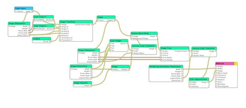
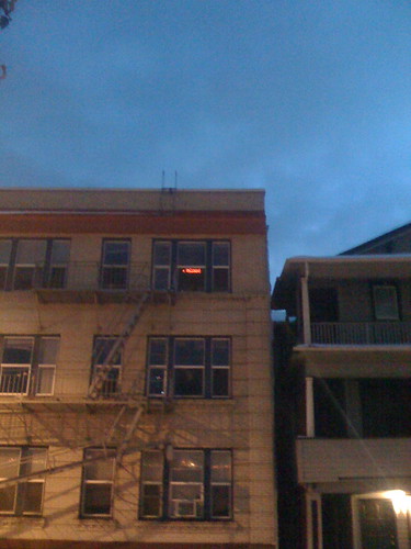
An example I have been working with takes a camera that I had on a pole with a motor that moved it around like a periscope. The camera is sideways so the view has to be rotated. I did this by hand using Core Image this summer using filters and transforms but wanted to do it in Quartz Composer. The composition looks like this.
And the resulting image like this.
On the way down to UCSF last month I experimented with some code that embeds a quartz composition into an application.
Most all of the work is done by adding your composition to the xcode project and then placing a Quartz Composer View (QCView) from the objects library in your window using Interface builder. The only code I needed to make my application usable (to take pictures) was the action to save the view to a file.
I recently fixed some issues with the benito arduino programmer and upgraded it to the latest version of the LUFA library. I hadnt noticed that there was a miss match between the .inf and the library supplied descriptors. My appoligies to the two xp users. As this is the only batch with this issue I will reprogram the boards that I currently have. In the mean time this can be fixed by changing the following line in the current driver file from:
The Second session of the induction is getting close to 20 prepayed people so if you havent rsvpd please do so soon (either bring check/money to the meeting monday or paypal $25 to cult /at/ tempusdictum.com)
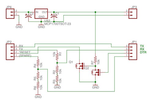
When looking for interface examples for the xbee I found a site that started out with a circuit from maxstream and then once everything was working tried a resistor based voltage divider. This is how I got my first set of x-bees running via the ftdi chips.
One thing that this circuit didn’t do for me was to provide a decent pull-down for the reset. The 2 transistors on the right of this circuit are an attempt to do just that.
Another Way: Run everything at 3.3v
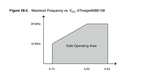
If you look at the datasheet for the atmega168 you will find the following diagram.
Looking at this you can see that 16mhz may or may not be in the operating range at 3.3v. But if you drop the crystal down to 8mhz you are good for sure. You may have to change a few things but it is doable.
The Ever Illusive Third: Buffers.
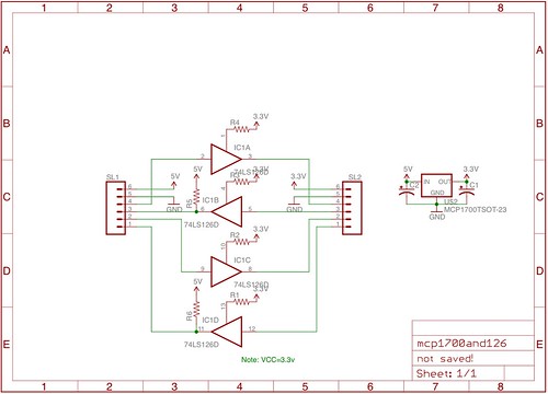
The idea of adding another layer at each intervace between boards can have you asking for some Tzatziki and falafel to go with the PITA. There are buffers which are designed specifcally for this. Many of the odd, many of them expensive. But there are also many families of buffer which are “tolerant” of a range of voltages outside of their supply. One of the buffers I checked out was the 74abt126 which is a tri state buffer. (I was looking at that because with the tristate buffers you can actually do a two way buffer by selecting the direction). I am not entirely certain that the 5v recieve side is kosher with these.
The other buffers I am looking at with 5v tolerant i/o are the 74lvc125 and 74lvc126. These are 3.6v native parts with 5v “tolerant” io.
Since I ordered the wrong series of parts last group order I will have to wait a week to check this out.
I have a few devices that I need to interface to either the benito or another avr board that run at 3.3v. one is an ethernet interface, one is a bluetooth modem and then there are the x-bees.
One Way: Simple Voltage Divider.
When looking for interface examples for the xbee I found a site that started out with a circuit from maxstream and then once everything was working tried a resistor based voltage divider. This is how I got my first set of x-bees running via the ftdi chips.
One thing that this circuit didn’t do for me was to provide a decent pull-down for the reset. The 2 transistors on the right of this circuit are an attempt to do just that.
Another Way: Run everything at 3.3v
If you look at the datasheet for the atmega168 you will find the following diagram.
Looking at this you can see that 16mhz may or may not be in the operating range at 3.3v. But if you drop the crystal down to 8mhz you are good for sure. You may have to change a few things but it is doable.
The Ever Illusive Third: Buffers.
The idea of adding another layer at each interface between boards can have you asking for some Tzatziki and falafel to go with the PITA. There are buffers which are designed specifically for this. Many of the odd, many of them expensive. But there are also many families of buffer which are “tolerant” of a range of voltages outside of their supply. One of the buffers I checked out was the 74abt126 which is a tri state buffer. (I was looking at that because with the tristate buffers you can actually do a two way buffer by selecting the direction). I am not entirely certain that the 5v receive side is kosher with these.
The other buffers I am looking at with 5v tolerant i/o are the 74lvc125 and 74lvc126. These are 3.6v native parts with 5v “tolerant” io.
Since I ordered the wrong series of parts last group order I will have to wait a week to check this out.
As part of getting the new workspace space I moved the toxins related to casting and circuit board fabrication out of my apartment. The theory being that the space is semi industrial.
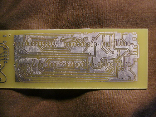
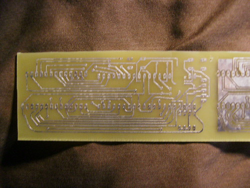
So as a test of the new space I took one of Alex Normans board designs and etched it.
Since the last time I worked with Alex on his designs he has picked up quite a bit and I only spent about 10 minutes getting his eagle files layed out and printed before going to the office. When I got there I realized that I had forgotten the green trf and bon ami but we were still able to get a reasonable etch and the new space has been broken in on the practice side.
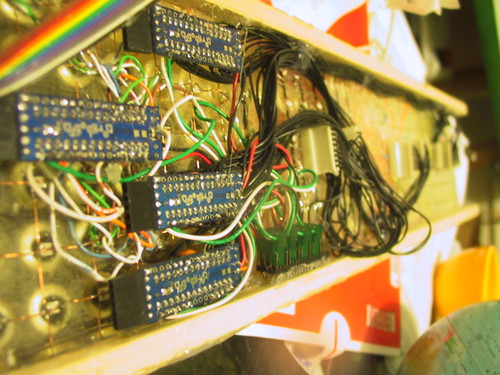
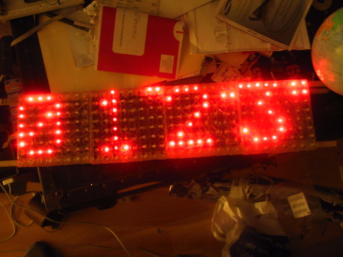
Last year I cast a series of led arrays for thing-a-day but hadnt wired them up. With this in mind I ordered some hc595s in the last group order but the snow canceled the meeting.
I have been thinking about using the avr to drive the arrays directly and control them using i2c. I hacked 4 dorkboards by cutting the traces for pins 5-12 on the top of the board and soldering 220 ohm resistors on the other side. This gives a one chip solution which does not require a constant refresh or other attention.
/*
 Simple 4 node array of leds (8x8).
 */
#include <Wire.h>

int node=0; /* CHANGE THIS BASED ON POSITION OF ARRAY */

volatile int twi_group_offset=128;

volatile int colpins[]={//12,11,10,9,8,7,6,5};
5,6,7,8,9,10,11,12};
volatile int rowpins[]={
17,16,15,14,13,4,3,2};
//2,3,4,13,14,15,16,17};

volatile unsigned long int myTics;

unsigned char pixels[]={0x3E, 0x51, 0x49, 0x45, 0x3E,0,0,node,
0x00, 0x42, 0x7F, 0x40, 0x00,0,1,1,
0x42, 0x61, 0x51, 0x49, 0x46,0,2,2,
0x21, 0x41, 0x45, 0x4B, 0x31,0,3,3
};

void setup()                    // run once, when the sketch starts
{

	int i;
	myTics=millis();
	for(i=0;i<8;i++){
		pinMode(rowpins[i],OUTPUT);
		digitalWrite(rowpins[i],LOW);
		pinMode(colpins[i],OUTPUT);
		digitalWrite(colpins[i],HIGH);
	}    // sets the digital pin as output
	if (node==0) {
		Wire.begin();
		Serial.begin(19200);
		updateSlaveNodes();
	} else {
		Wire.begin(node+twi_group_offset);
		Wire.onReceive(updatePixels); // register event
	}
}

void loop()                    //move most of this into a timer loop.
{
	int r,c;
	int lastcolpin=colpins[0];
	for (c=0;c<8;c++){
		lastcolpin=colpins[c];
		for(r=0;r<8;r++){
			if ((pixels[c]>>r)&0x01){
				//if ((!r)||((7-c)==r)||(c==r)){
				digitalWrite(rowpins[r], HIGH);
			} else {
				digitalWrite(rowpins[r], LOW);
			}
		}
		digitalWrite(colpins[c], LOW);
		if (node==0) {
			updateSlaveNodes();
		} else {
			//delayMicroseconds(1500); //
			delay(3);
		}
		digitalWrite(lastcolpin, HIGH);
	}
}

void updateSlaveNodes() {
	int slavenode, row, pixel8;
	pixel8=8;
	for (slavenode=1;slavenode<4;slavenode++){
		Wire.beginTransmission(slavenode+twi_group_offset);
		for (row=0;row<8;row++) {
			Wire.send(pixels[pixel8++]);
		}
		Wire.endTransmission();
	};
}

// function that executes whenever data is received from master
// this function is registered as an event, see setup()
void updatePixels(int howMany)
{ int r=0;
	while(Wire.available()) //
	{
		pixels[r++] = Wire.receive(); // receive byte as a character
	}
}
The next step is to move the actual refresh into a timer routine so that the body of code for the main node can focus on content.
/*------------------------------------------------------------ xmas timer array
*
* This is the program for a 4x8x8 led display using a processor for each segment
* To program the different nodes set the node variable below. Node 0 is the
* master node which keeps the pixel memory for the remaining nodes.
*
* The master node takes its memory and sends updates to each of the other segments
* via the i2c buss using the Wire library.
*
* Each node takes its 8byte array of data and strobes it onto the display using
* the 8 bit timer2 overflow interrupt.
*
* The first 7 characters are loaded into the display memory using the
* loadCharacters function. The array is then shifted to the left in the main loop
* with the next character being loaded a collumn at a time.
*
* The character data and the bitmap for the 5x7 array are stored in program
* memory.
*
* Since interrupts are used all of the globals are marked as volatile.
*
* CopyLeft 2008 Donald Delmar Davis, Tempus Dictum, Inc.
* This is free software (GPL)
*/
#include <Wire.h>
#include <avr/interrupt.h>
#include <avr/io.h>
#include <avr/pgmspace.h>
#define FREEK 180
int node=0; /* CHANGE THIS BASED ON POSITION OF ARRAY */
unsigned char PROGMEM Font5x7[] = {
0x00, 0x00, 0x00, 0x00, 0x00,// (space)
0x00, 0x00, 0x5F, 0x00, 0x00,// !
0x00, 0x07, 0x00, 0x07, 0x00,// "
0x14, 0x7F, 0x14, 0x7F, 0x14,// #
0x24, 0x2A, 0x7F, 0x2A, 0x12,// $
0x23, 0x13, 0x08, 0x64, 0x62,// %
0x36, 0x49, 0x55, 0x22, 0x50,// &
0x00, 0x05, 0x03, 0x00, 0x00,// '
0x00, 0x1C, 0x22, 0x41, 0x00,// (
0x00, 0x41, 0x22, 0x1C, 0x00,// )
0x08, 0x2A, 0x1C, 0x2A, 0x08,// *
0x08, 0x08, 0x3E, 0x08, 0x08,// +
0x00, 0x50, 0x30, 0x00, 0x00,// ,
0x08, 0x08, 0x08, 0x08, 0x08,// -
0x00, 0x60, 0x60, 0x00, 0x00,// .
0x20, 0x10, 0x08, 0x04, 0x02,// /
0x3E, 0x51, 0x49, 0x45, 0x3E,// 0
0x00, 0x42, 0x7F, 0x40, 0x00,// 1
0x42, 0x61, 0x51, 0x49, 0x46,// 2
0x21, 0x41, 0x45, 0x4B, 0x31,// 3
0x18, 0x14, 0x12, 0x7F, 0x10,// 4
0x27, 0x45, 0x45, 0x45, 0x39,// 5
0x3C, 0x4A, 0x49, 0x49, 0x30,// 6
0x01, 0x71, 0x09, 0x05, 0x03,// 7
0x36, 0x49, 0x49, 0x49, 0x36,// 8
0x06, 0x49, 0x49, 0x29, 0x1E,// 9
0x00, 0x36, 0x36, 0x00, 0x00,// :
0x00, 0x56, 0x36, 0x00, 0x00,// ;
0x00, 0x08, 0x14, 0x22, 0x41,// <
0x14, 0x14, 0x14, 0x14, 0x14,// =
0x41, 0x22, 0x14, 0x08, 0x00,// >
0x02, 0x01, 0x51, 0x09, 0x06,//
0x32, 0x49, 0x79, 0x41, 0x3E,// @
0x7E, 0x11, 0x11, 0x11, 0x7E,// A
0x7F, 0x49, 0x49, 0x49, 0x36,// B
0x3E, 0x41, 0x41, 0x41, 0x22,// C
0x7F, 0x41, 0x41, 0x22, 0x1C,// D
0x7F, 0x49, 0x49, 0x49, 0x41,// E
0x7F, 0x09, 0x09, 0x01, 0x01,// F
0x3E, 0x41, 0x41, 0x51, 0x32,// G
0x7F, 0x08, 0x08, 0x08, 0x7F,// H
0x00, 0x41, 0x7F, 0x41, 0x00,// I
0x20, 0x40, 0x41, 0x3F, 0x01,// J
0x7F, 0x08, 0x14, 0x22, 0x41,// K
0x7F, 0x40, 0x40, 0x40, 0x40,// L
0x7F, 0x02, 0x04, 0x02, 0x7F,// M
0x7F, 0x04, 0x08, 0x10, 0x7F,// N
0x3E, 0x41, 0x41, 0x41, 0x3E,// O
0x7F, 0x09, 0x09, 0x09, 0x06,// P
0x3E, 0x41, 0x51, 0x21, 0x5E,// Q
0x7F, 0x09, 0x19, 0x29, 0x46,// R
0x46, 0x49, 0x49, 0x49, 0x31,// S
0x01, 0x01, 0x7F, 0x01, 0x01,// T
0x3F, 0x40, 0x40, 0x40, 0x3F,// U
0x1F, 0x20, 0x40, 0x20, 0x1F,// V
0x7F, 0x20, 0x18, 0x20, 0x7F,// W
0x63, 0x14, 0x08, 0x14, 0x63,// X
0x03, 0x04, 0x78, 0x04, 0x03,// Y
0x61, 0x51, 0x49, 0x45, 0x43,// Z
0x00, 0x00, 0x7F, 0x41, 0x41,// [
0x02, 0x04, 0x08, 0x10, 0x20,// ""
0x41, 0x41, 0x7F, 0x00, 0x00,// ]
0x04, 0x02, 0x01, 0x02, 0x04,// ^
0x40, 0x40, 0x40, 0x40, 0x40,// _
0x00, 0x01, 0x02, 0x04, 0x00,// `
0x20, 0x54, 0x54, 0x54, 0x78,// a
0x7F, 0x48, 0x44, 0x44, 0x38,// b
0x38, 0x44, 0x44, 0x44, 0x20,// c
0x38, 0x44, 0x44, 0x48, 0x7F,// d
0x38, 0x54, 0x54, 0x54, 0x18,// e
0x08, 0x7E, 0x09, 0x01, 0x02,// f
0x08, 0x14, 0x54, 0x54, 0x3C,// g
0x7F, 0x08, 0x04, 0x04, 0x78,// h
0x00, 0x44, 0x7D, 0x40, 0x00,// i
0x20, 0x40, 0x44, 0x3D, 0x00,// j
0x00, 0x7F, 0x10, 0x28, 0x44,// k
0x00, 0x41, 0x7F, 0x40, 0x00,// l
0x7C, 0x04, 0x18, 0x04, 0x78,// m
0x7C, 0x08, 0x04, 0x04, 0x78,// n
0x38, 0x44, 0x44, 0x44, 0x38,// o
0x7C, 0x14, 0x14, 0x14, 0x08,// p
0x08, 0x14, 0x14, 0x18, 0x7C,// q
0x7C, 0x08, 0x04, 0x04, 0x08,// r
0x48, 0x54, 0x54, 0x54, 0x20,// s
0x04, 0x3F, 0x44, 0x40, 0x20,// t
0x3C, 0x40, 0x40, 0x20, 0x7C,// u
0x1C, 0x20, 0x40, 0x20, 0x1C,// v
0x3C, 0x40, 0x30, 0x40, 0x3C,// w
0x44, 0x28, 0x10, 0x28, 0x44,// x
0x0C, 0x50, 0x50, 0x50, 0x3C,// y
0x44, 0x64, 0x54, 0x4C, 0x44,// z
0x00, 0x08, 0x36, 0x41, 0x00,// {
0x00, 0x00, 0x7F, 0x00, 0x00,// |
0x00, 0x41, 0x36, 0x08, 0x00,// }
0x08, 0x08, 0x2A, 0x1C, 0x08,// ->
0x08, 0x1C, 0x2A, 0x08, 0x08 // <-
};
unsigned char PROGMEM banner[] = "Happy Holidays!!! Merry Christmas!!! May every man with "Merry Christmas" on his lips be boiled in his own blood pudding with a steak of holly driven through his heart! Christmas! BAH! HUMBUG!!!";
volatile int twi_group_offset=128;
volatile int colpins[]={5,6,7,8,9,10,11,12};
volatile int rowpins[]={17,16,15,14,13,4,3,2};
volatile unsigned long int myTics; //counter for timer interrupt.
volatile unsigned char pixels[]={
0x3E, 0x51, 0x49, 0x45, 0x3E,0,0,node,
0x00, 0x42, 0x7F, 0x40, 0x00,0,0,1,
0x42, 0x61, 0x51, 0x49, 0x46,0,0,2,
0x21, 0x41, 0x45, 0x4B, 0x31,0,0,3,
0x00, 0x00, 0x00, 0x00, 0,0,0,0}; //pixel buffer rounded out to another 8 bytes
volatile unsigned int cursorpos=0;
volatile unsigned int charcursor=0;
volatile unsigned int currentcol;
volatile unsigned int charmod;
volatile unsigned char currentchar;
volatile unsigned int currentcharoffset;
/*---------------------------------------------------------------------setup()
* initialize timer2
* setup the i/o pins (initialized with everything off);
* Initialize the i2c buss;
* if master node then load initial characters into display.
*/
void setup() // run once, when the sketch starts
{
int i;
currentcol=0;
/*------------ setting up timer two. ----------------*/
TCCR2A = 0; // normal mode
TCCR2B = 1<<CS22 | 1<<CS21 | 0<<CS20; // clock selection
TIMSK2 |= 1<<TOIE2; // enable overflow interupt
TCNT2=FREEK; // adjustment of period
ASSR=0; // paranoid
myTics=0; // counter for delays
sei(); // enable interrupts
for(i=0;i<8;i++){
pinMode(rowpins[i],OUTPUT);
digitalWrite(rowpins[i],LOW);
pinMode(colpins[i],OUTPUT);
digitalWrite(colpins[i],HIGH);
}
if (node==0) { // master node
Wire.begin();
Serial.begin(19200);
loadCharacters();
updateSlaveNodes();
} else {
Wire.begin(node+twi_group_offset);
Wire.onReceive(updatePixels); // register event
}
}
/*------------------------------------------------------------ISR(TIMER2_OVF_vect)
* loads the next collumn into the led array
*
*/
ISR(TIMER2_OVF_vect) {
int r;
digitalWrite(colpins[currentcol], HIGH); //turn off the last column.
if (++currentcol > 7) {
currentcol=0;
}
for(r=0;r<8;r++){
if ((pixels[currentcol]>>r)&0x01){
digitalWrite(rowpins[r], HIGH);
} else {
digitalWrite(rowpins[r], LOW);
}
}
digitalWrite(colpins[currentcol], LOW);
myTics++;
TCNT2 = FREEK;
};
/*--------------------------------------------------------------loadCharacters()
* load the initial characters into the pixel buffer
*/
void loadCharacters(){
int ch,i,j;
cursorpos=0;
for (charcursor=0;charcursor<7;charcursor++) {
ch=pgm_read_byte_near(banner+charcursor);
j= (ch-32) & 0x000000ff;
j = j*5;
for (charmod=0;charmod<5;charmod++){
pixels[cursorpos++]=pgm_read_byte_near(Font5x7+j+charmod);
}
}
}
/*------------------------------------------------------------updateSlaveNodes()
* send the pixel data to the slave nodes.
*/
void updateSlaveNodes() {
int slavenode, row, pixel8;
if (node==0) {
pixel8=8;
for (slavenode=1;slavenode<4;slavenode++){
Wire.beginTransmission(slavenode+twi_group_offset);
for (row=0;row<8;row++) {
Wire.send(pixels[pixel8++]);
}
Wire.endTransmission();
};
}
}
/*------------------------------------------------------------------udatePixels()
* recieve the pixel data from the master node.
* executes whenever data is received from master
* this function is registered as an event, see setup()
*/
void updatePixels(int ignored)
{ int r=0;
while(Wire.available()) //
{
pixels[r++] = Wire.receive(); // receive byte as a character
}
}
/*-------------------------------------------------------------------------loop()
*
*/
void loop()
{int c;
//int head=pixels[0];
updateSlaveNodes();
for (c=1;c<35;c++) {
pixels[c-1]=pixels[c];
}
if (charmod==5) {//get next char
charcursor++;
charmod=0;
currentchar=pgm_read_byte_near(banner+charcursor);
if (currentchar=='�'){
currentchar=pgm_read_byte_near(banner);
charcursor=0;
}
currentcharoffset = (currentchar-32) & 0x000000ff;
currentcharoffset = currentcharoffset*5;
}
pixels[34]=pgm_read_byte_near(Font5x7+currentcharoffset+charmod);
charmod++;
while (myTics<90) ; myTics=0L; //wait a few hundred millisecconds
}
 iSight Periscope
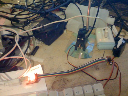 USB to Servo Controller
 View from the Periscope