by on reference

I wanted to quickly demonstrate using a stepper motor from a floppy drive with the Arduino/Wiring platform as a follow up to the weekend’s workshop. By the time we got to the stepper parts I was a bit scattered. So here is an example that I set up yesterday.

I have a talking George Bush doll from several years ago that was ripped in half (by people watching my punk band (w.busholini.org)) so I went ahead and finished dismantling it. For Halloween I thought his head should turn around Linda Blair style.

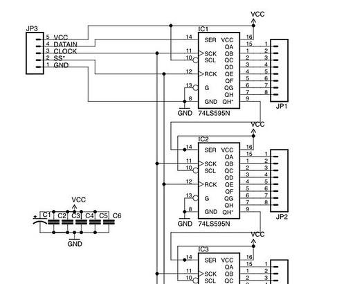
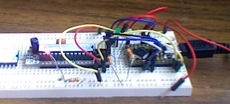
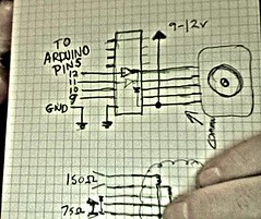
I wired up a ULN2803 Darlington array and a floppy drive stepper motor from the workshop as shown in the diagram above .

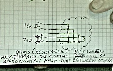
I figured out which wire was the common wire by taking an ohmmeter to the wires on the stepper. Most of the combinations were about 150 except from one of the wires on the end that read 75 ohms. Checking the 75 against all of the other wires I was able to determine that one of the wires was the common one and marked it with a sharpie.

Then I ran up the arduino (v 17) example program for the stepper library. I modified it so that it just made steps in one direction. When I ran it the motion was really jittery so I checked to make sure that my wiring was good and then rather than rewiring the stepper physically I changed the line in the code from

Stepper stepper(STEPS, 9, 10, 11, 12);

to

Stepper stepper(STEPS, 9, 11, 10,12);

And Whah La! his head started spinning just like he was possessed by Dick Cheney! I wired the talk button to pin 8 and then added some random delays which gave me the following.

#include <Stepper.h>

// change this to the number of steps on your motor
#define STEPS 100
int relayPin=8;
int ledPin=13;
// create an instance of the stepper class, specifying
// the number of steps of the motor and the pins it's
// attached to
Stepper stepper(STEPS, 9, 11, 10,12);

// the previous reading from the analog input
int previous = 0;

void setup()
{ pinMode(relayPin,OUTPUT);
  pinMode(ledPin,OUTPUT);
  // set the speed of the motor to 30 RPMs
  stepper.setSpeed(100);
}

void loop()
{
  // get the sensor value
  int val = analogRead(0);

  // move a number of steps equal to the change in the
  // sensor reading
  //stepper.step(val - previous);
digitalWrite(ledPin, HIGH);
stepper.step(random(5,90));
delay(random(60,2000));
digitalWrite(relayPin, HIGH);
delay(20);
digitalWrite(relayPin, LOW);
digitalWrite(ledPin, LOW);
stepper.step(-random(15,200));
delay(random(90,3000));
  // remember the previous value of the sensor
  previous = val;
}

by on Dorkbot


On Sunday the 25th I am going to do an animtronicx workshop covering driving
motors, servos and relays with the arduino/wiring platform.
I will be covering the a couple of popular chips: The l293D for
driving motors , and the ULN2803 darlington array for driving relays,
stepper motors and other devices.
The workshop will cost $35 and will include these chips, a motor, a standard sized servo and a board for the motor driver.

The idea is to get as much hands on and working as possible so please
bring your arduino,freeduino,teensy,or dorkboard, a soldering iron, some wire and your
laptop and we will get our hands dirty.
I am limited to 25 on this one so please RSVP as soon as possible.


http://tempusdictum.com/tdproducts.html

This will be in room 205 at PNCA (NW 12th and Johnson) from 1-5 pm.

by on Dorkbot

A while back I started thinking about a way to display stationary bike race results that didn’t require either a projector or a really complicated mechanical assembly. The thing that came to mind was a race tree like at the drag races. I asked Amanda who has been running bike events in portland if she could get me 12 lights. I wound up with pile of Bike Planet lights which required about a weeks worth of surgery.

From one of our led driving discussions a few years back I wound up with a tube of 74hc595s which I wired up like so.

While there are examples using bit banging to drive shift registers with the arduino they ignore the built in hardware capabilities of the AVR family.

Using the built in spi greatly simplifies your code and is remarkably fast. In the code sample below there are 5 bytes which represent the 40 pins from 5 shift registers. The main loop just toggles the bits and sends them out the door.

byte outbytes[5]={0x55,0x55,0x55,0x55,0x55};
//uncomment this for a standard arduino
//#define PIN_SCK          13             // SPI clock (also Arduino LED!)
//#define PIN_MISO         12             // SPI data input
//#define PIN_MOSI         11             // SPI data output#define PIN_HEARTBEAT     7           // added LED
#define PIN_SCK          9           // SPI clock (also Arduino LED!)
#define PIN_MISO         11            // SPI data input
#define PIN_MOSI         10          // SPI data output
#define PIN_SS         8             // SPI slave select

void EnableSPI(void) {
SPCR |= 1 << SPE;
}

void DisableSPI(void) {
SPCR &= ~(1 << SPE);
}

byte SendRecSPI(byte Dbyte) {             // send one byte, get another in exchange
SPDR = Dbyte;
while (! (SPSR & (1 << SPIF))) {
continue;
}
return SPDR;                             // SPIF will be cleared
}

void RunShiftRegister(void) {
byte bitBucket;
int i;
digitalWrite(PIN_SS,HIGH);
EnableSPI();                             // turn on the SPI hardware
for (i=0; i<5; i++) {
bitBucket = SendRecSPI(outbytes[i]);
}
DisableSPI();                             // return to manual control
digitalWrite(PIN_SS,LOW);

}

void setup() {

pinMode(PIN_SCK,OUTPUT);
digitalWrite(PIN_SCK,LOW);
pinMode(PIN_SS,OUTPUT);
digitalWrite(PIN_SS,HIGH);
pinMode(PIN_MOSI,OUTPUT);
digitalWrite(PIN_MOSI,LOW);
pinMode(PIN_MISO,INPUT);
digitalWrite(PIN_MISO,HIGH);

SPCR = B01110001;              // Auto SPI: no int, enable, LSB first, master, + edge, leading, f/16
SPSR = B00000000;              // not double data rate

}

void loop(){
int i;
RunShiftRegister();
for (i=0; i<5; i++){
outbytes[i]= ~outbytes[i];
}
delay(1000);
};

Simple fast and easy.

by on reference

A while back I started thinking about a way to display stationary bike race results that didn’t require either a projector or a really complicated mechanical assembly. The thing that came to mind was a race tree like at the drag races. I asked Amanda who has been running bike events in portland if she could get me 12 lights. I wound up with pile of Bike Planet lights which required about a weeks worth of surgery.

From one of our led driving discussions a few years back I wound up with a tube of 74hc595s which I wired up like so.

While there are examples using bit banging to drive shift registers with the arduino they ignore the built in hardware capabilities of the AVR family.

Using the built in spi greatly simplifies your code and is remarkably fast. In the code sample below there are 5 bytes which represent the 40 pins from 5 shift registers. The main loop just toggles the bits and sends them out the door.

byte outbytes[5]={0x55,0x55,0x55,0x55,0x55};
//uncomment this for a standard arduino
//#define PIN_SCK          13             // SPI clock (also Arduino LED!)
//#define PIN_MISO         12             // SPI data input
//#define PIN_MOSI         11             // SPI data output#define PIN_HEARTBEAT     7           // added LED
#define PIN_SCK          9           // SPI clock (also Arduino LED!)
#define PIN_MISO         11            // SPI data input
#define PIN_MOSI         10          // SPI data output
#define PIN_SS         8             // SPI slave select

void EnableSPI(void) {
SPCR |= 1 << SPE;
}

void DisableSPI(void) {
SPCR &= ~(1 << SPE);
}

byte SendRecSPI(byte Dbyte) {             // send one byte, get another in exchange
SPDR = Dbyte;
while (! (SPSR & (1 << SPIF))) {
continue;
}
return SPDR;                             // SPIF will be cleared
}

void RunShiftRegister(void) {
byte bitBucket;
int i;
digitalWrite(PIN_SS,HIGH);
EnableSPI();                             // turn on the SPI hardware
for (i=0; i<5; i++) {
bitBucket = SendRecSPI(outbytes[i]);
}
DisableSPI();                             // return to manual control
digitalWrite(PIN_SS,LOW);

}

void setup() {

pinMode(PIN_SCK,OUTPUT);
digitalWrite(PIN_SCK,LOW);
pinMode(PIN_SS,OUTPUT);
digitalWrite(PIN_SS,HIGH);
pinMode(PIN_MOSI,OUTPUT);
digitalWrite(PIN_MOSI,LOW);
pinMode(PIN_MISO,INPUT);
digitalWrite(PIN_MISO,HIGH);

SPCR = B01110001;              // Auto SPI: no int, enable, LSB first, master, + edge, leading, f/16
SPSR = B00000000;              // not double data rate

}

void loop(){
int i;
RunShiftRegister();
for (i=0; i<5; i++){
outbytes[i]= ~outbytes[i];
}
delay(1000);
};

Simple fast and easy.

by on Dorkbot


WiiWah demo from Donald Delmar Davis on Vimeo.

Collin Oldham came over before my gig in Spokane last month and brought a couple of patches and a few ideas on how to set up an effects chain using pure data. One of them was a patch using something called a “Formant” filter.

Wah.

I am not going to even pretend to understand it. But when I actually got to where I could play with it, it was really subtle and I didn’t like it. Then Collin explained that it needed some harmonics to work well.

Crunchy

Lucky for me Jason (breedx) showed me a really nice technique for getting distortion. Its still not as nice as my gz2 but its a pretty good demo of some of what can be done very easily in pure data.

Combining the two creates a really nice wah that is very vowel like as you can hear in the video above.

Connecting the Wiimote to pd on a mac.

My first attempt to connect to pd using the wii was using an OSC connection called musiccontroller using my intel mac. It worked though had the same issues that darwin remote has where in order to reconnect the wiimote to the you had to manually delete the binding that osx creats for the wiimote in the bluetooth control panel. The show stopper though was that it did not run on the machine I am targeting which is running tiger on a PPC.

Looking at alternatives I found a program called OSCulator which has ability to map multiple input sources and wiimotes, connects to the wiimote consistantly and with very little intervention and it has an extremely flexible mapping system for both osc and midi (though I never did get the osc part to work). It was however was neither open source nor free.

The solution I wound up with both simple and straight forward. It uses an open source application called wiitomidi and OSX’s IAC loopback device.

The pd source for all the patches put together is attached here. (http://dorkbotpdx.org/files/wiiwah.tgz)

by on Dorkbot

When I created the Benito I was working on a specific need for an arduino “programmer”. Since then several products have come out which are comparable and in some cases less expensive than the manual labor it takes me to build out and program the boards. One of these is the bumble-b. from Dave Fletcher. For this months arduino cult induction I will be evaluating the bumble-b as a possible replacement.

If you want to check out the bumble-b yourself I have 20 of them at a dorkbotpdx introductory rate of $10 which I will bring to Monday’s meeting.

See also

by on Dorkbot

When I first built the box above I was trying to overcome the things I disliked about one of my better effect systems. It is a zoom bass pedal with several programmable subsystems (reverb/delay/distortion/a couple of lfos and filters) which you put together using an amazingly arcane system to get a huge variety of sounds. Of course once you unplug it it looses your programming and you are left with the factory presets. Which once you get over your loss isn’t so bad in itself since about a fifth of the “stock” sounds are all you would ever need. The thing that stinks is hunting and pecking for them.

I wanted to put together using pure data a similar “set” of sounds that I could select, combine and adjust easily. I started with a 4 button/slider prototype and laid out a 16 button/slider board which I managed to mess up in the gimp as to make it unusable.

So I put the prototype into production. I recycled the box that I originally tried to put all of the imic / gk-3 interface into (a disaster at best probably never to be explained before blowing up a mini itx motherboard in an attempt build out an audiopint, so it goes) and mounted everything as below.

All of the pots and lighted switches are actual musical instrument components. For the stomp switches I used the same interface (rca jacks) that the switches originally used to select effects on an old tube amp. For the expression I used an unmodified volume/pan peddle.

Then I went about getting it interfaced to pure data.

The easiest path to this was using Paul Stoffregon’s fresh port of firmata and a teensy++. I chose this because there are ample examples and it is established. Because the arduino is by default stupidly serial only I knew that I would be moving up the chain to something more usable like usb native midi but I didn’t have time to write the underlying firmware and then figure out how to use it to control pd.

Firmata delivered what it was supposed to with a few exceptions.

  1. No debounce on the switches.
  2. No pullups on the inputs.
  3. Its noisy and puts a lot of data out.

The first two were easy enough to fix. There is a de-bounce abstraction in pd extended that more or less works and I added the pullups to the input setup in the firmata. I would run this back up the source but first of all this is not the best solution and the last issue was pretty much a showstopper. There is a lot of meticulous work in the firmata library designed specifically to get data out quickly and when you combine that with a usb/serial implimentation that is not limited by actual serial speeds the result is a *lot* of data (95 percent of which you dont need). On a 2.1 Ghz macbook with 4 gig of memory, a noisy potentiometer would actually put out enough data to where there were audible glitches in the sound.

So I started looking at alternatives including Collin Oldham’s recent blog post (http://www.dorkbotpdx.org/blog/coldham/pd_and_arduino_or_whatever_you_call_it) until I found the link below.

http://kiilo.org/tiki/tiki-index.php?page=Arduino-PureData-MessageSystem

It wasnt perfect but it was close enough that I was able to make it fit my needs in a little over a day of hacking at it (with a little help from my friends of course).

The teensyduino code and the

pd patch are attached below.

by on Dorkbot

First let me thank the group of people who came on sunday for the first crack at the fabrication and circuit board workshop. I realize that we spent a lot of time in eagle and not enough time actually doing the etch process. In the future I will probably do a separate workshop for eagle alone.

For this reason I will be available Sunday at TDIs workshop at 833 SE Main #125 for any of yesterdays participants who would like to go over the process of etching the board again and to get some hands on practice.

You are also welcome to come to the TechShop session on june 14th (before carpooling to the dorkbot event at about us).

I have also uploaded the folder with the Anderton superfuzz design files ( http://dorkbotpdx.org/files/fabclass.zip ) and the hobby design rules You should try to run the drc error check and you should notice that with the wider pads a few of the parts will need to be moved.

The 1458 can be replaced with any of the following low noise equivalents (the lt and ne parts are spendy).

* http://search.digikey.com/scripts/DkSearch/dksus.dll?Detail&name=296-1410-5-ND
* http://search.digikey.com/scripts/DkSearch/dksus.dll?Detail&name=LT1113CN8%23PBF-ND
* http://search.digikey.com/scripts/DkSearch/dksus.dll?Detail&name=OPA2134UA/2K5E4-ND
* http://search.digikey.com/scripts/DkSearch/dksus.dll?Detail&name=296-1812-5-ND

For those of you who missed the session because you were away there will be a second session at techshop in the afternoon before the evenings event at about us.